Fastening device

a technology of fastening device and mounting plate, which is applied in the direction of fastening means, basic electric elements, washing machines, etc., can solve the problems of low engagement force between a male connection member and a female connection member, complicated installation operation, and conventional designs that cannot meet the actual requirements. , to achieve the effect of quick and firmly secured

Active Publication Date: 2015-09-08
MARINE TOWN
View PDF24 Cites 12 Cited by
  • Summary
  • Abstract
  • Description
  • Claims
  • Application Information

AI Technical Summary

Benefits of technology

[0008]To achieve these and other objects of the present invention, a fastening device comprises a resilient clamping member and a holder cup respectively stopped at opposing inner wall and outer wall of a support structure, a rubber female connector accommodated in the holder cup, a fastening member adjustably inserted through the rubber female connector, the holder cup and the resilient clamping member to control the relatively clamping position between the resilient clamping member and the holder cup, and a male connector fastened to a decorative ornamental panel and detachably fastenable to the rubber female connector for enabling the decorative ornamental panel to be quickly and firmly secured to the support structure.
[0010]Thus, the fastening device of the present invention facilitates mounting and dismounting for a wide range of applications. Because the fastening device is highly detachable, it facilitates maintenance work and has significant industrial value.

Problems solved by technology

However, if one mounting screw hole is not in perfect alignment, it is necessary to drill a new hole for mounting, complicating the installation operation.
Further, because regular male and female connection members are commonly made of plastics, the engagement force between a male connection member and a mating female connection member is low.
Further, during a dismounting operation, detaching a male connection member may cause the mating female connection member to be pulled out of place, resulting in component damage.
Further, after having been frequently mounted and dismounted, the tolerance between the male connection member and the mating female connection member will be expanded due to overfriction, affecting further matching stability and strength.
However, conventional designs do not allow relative adjustment to eliminate clearance between the decorative ornamental panel and the mounting wall, therefore, conventional designs cannot meet the actual requirements.

Method used


Image

  • Fastening device
  • Fastening device
  • Fastening device

Examples


Embodiment Construction

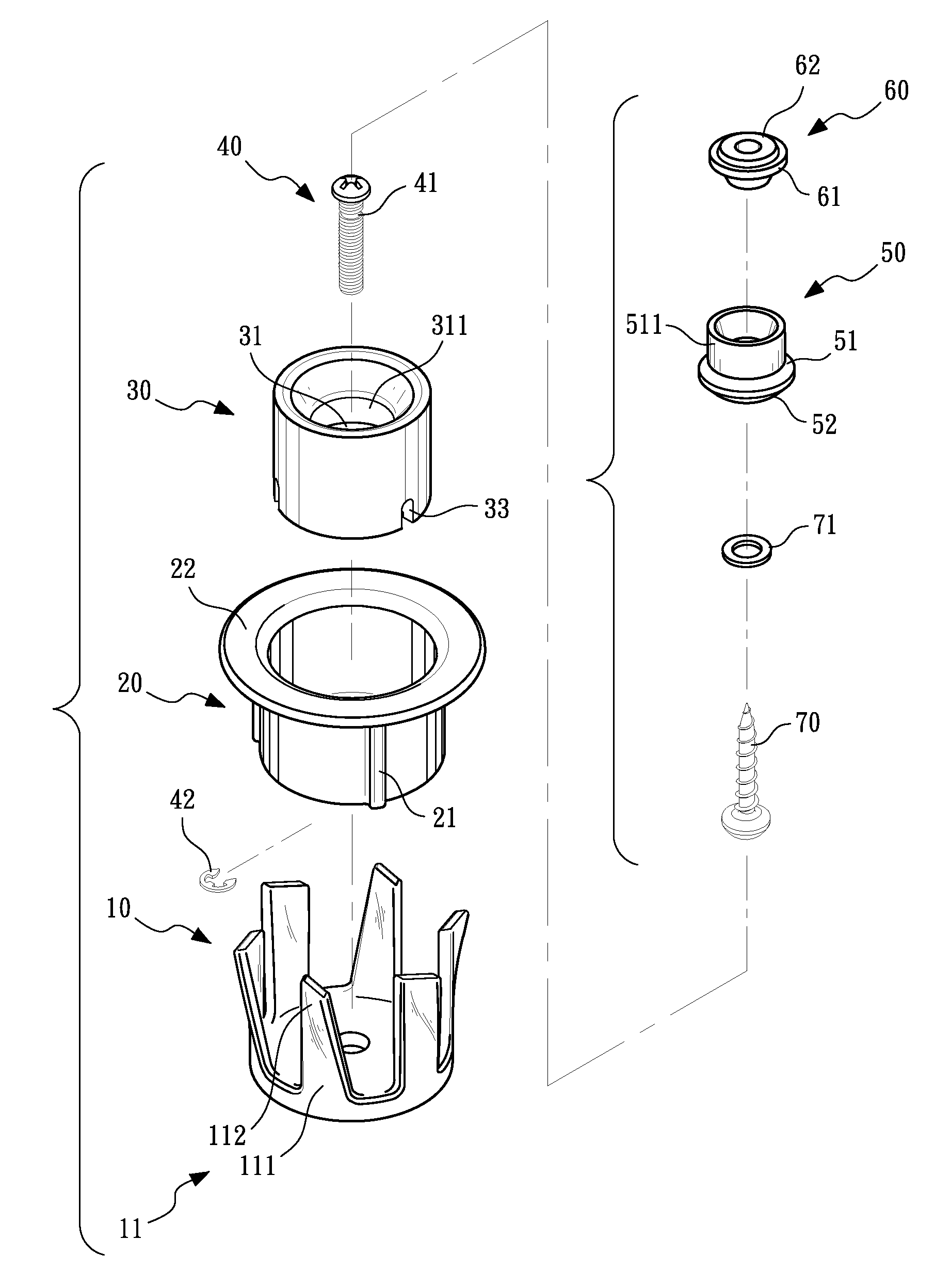
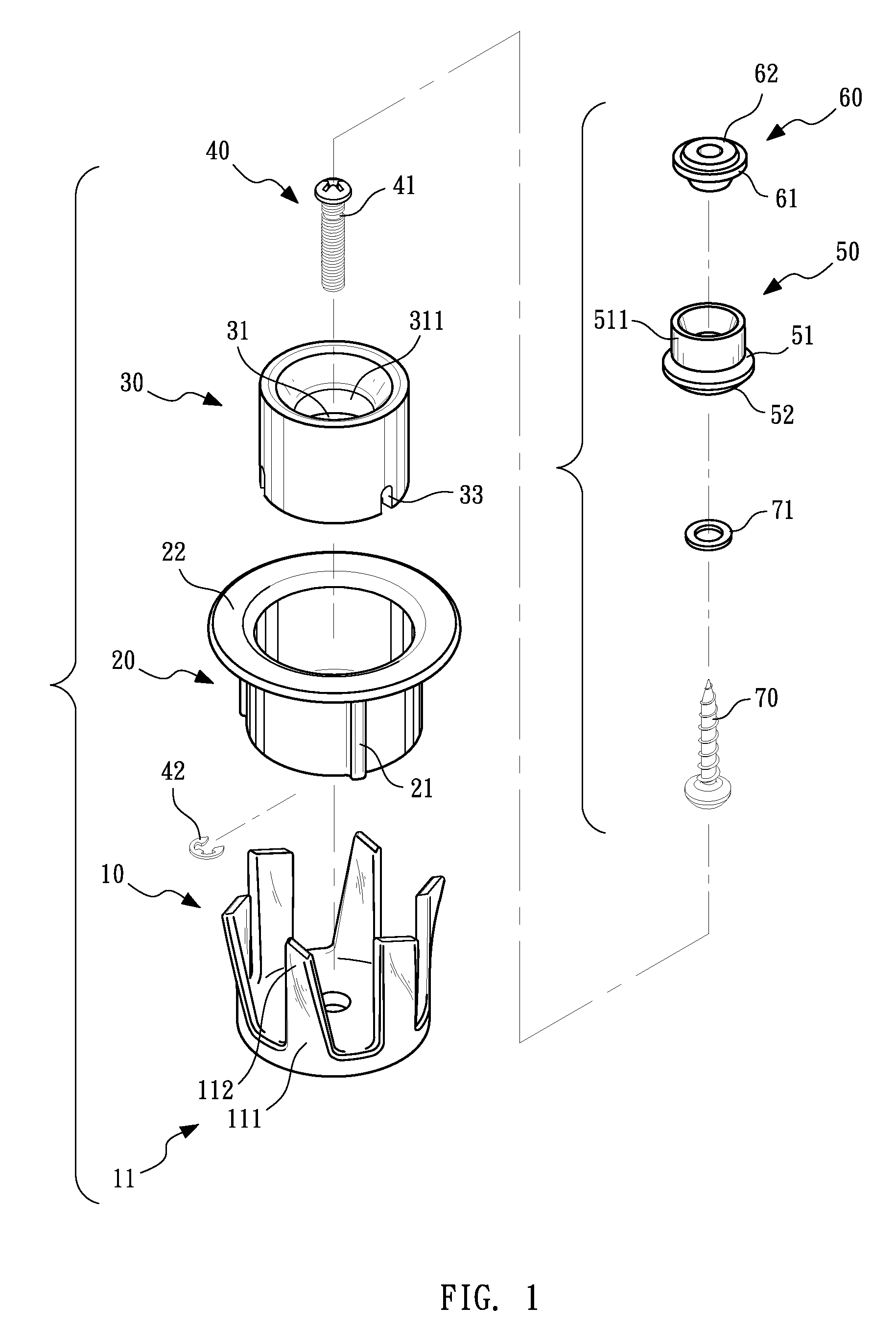
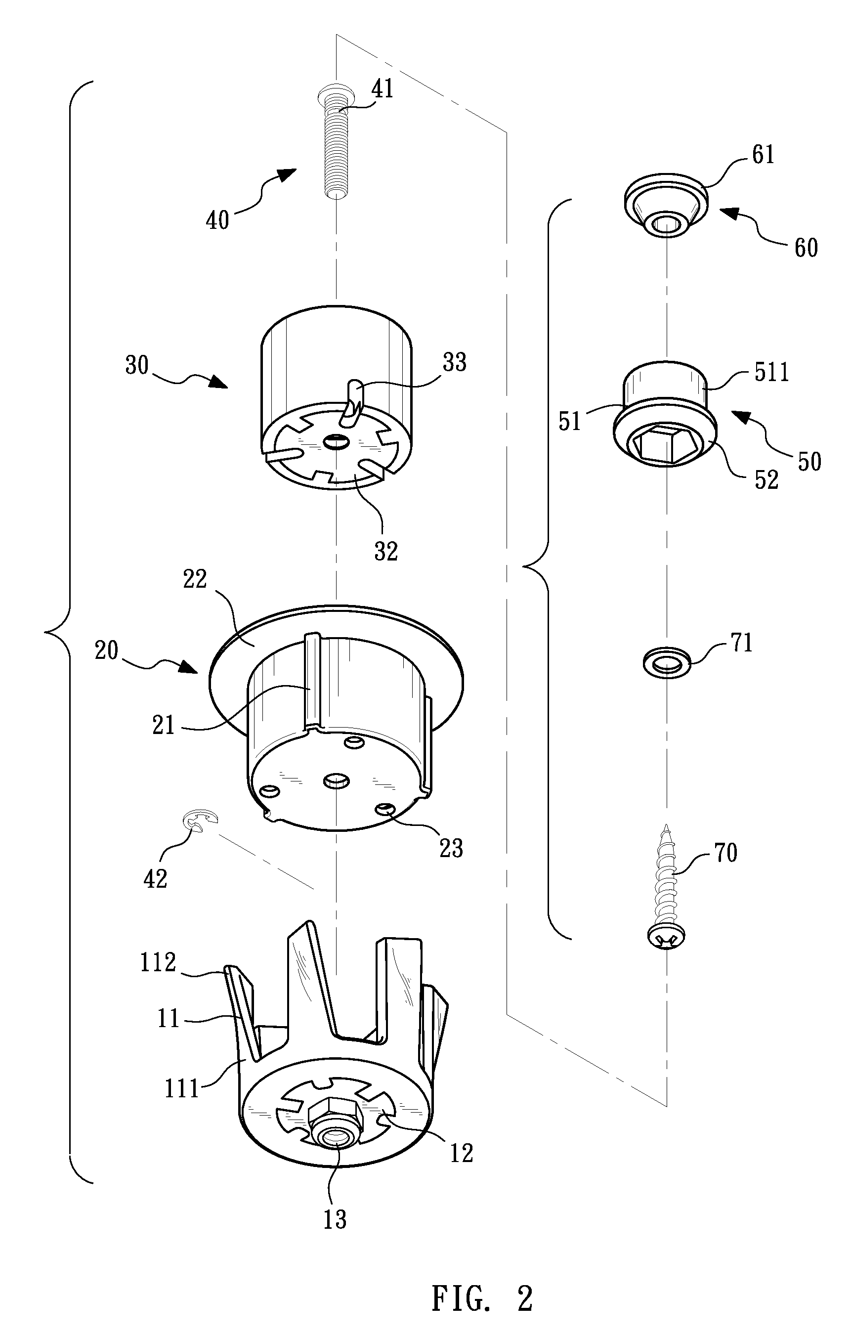
[0028]Referring to FIGS. 1-5, a fastening device in accordance with the present invention is shown. The fastening device comprises a resilient clamping member 10, a holder cup 20, a rubber female connector 30, a fastening member 40, and a male connector 50.

[0029]The resilient clamping member 10 is a plastic member comprising a plurality of equiangularly spaced clamping pawls 11. Each clamping pawl 11 defines a fixed end 111 and an opposing free end 112. The cross sectional area of the free end 112 is smaller than the cross-sectional area of the fixed end 111. Further, the free end 111 is gradually outwardly deflected in direction away from the fixed end 112.

[0030]Referring also to FIG. 3, the resilient clamping member 10 has embedded therein a first metal plate 12 and a screw nut 13. The resilient clamping member 10 and the first metal plate 12 are fixedly mounted together by insert molding, enhancing connection strength. The screw nut 13 is bonded to one side of the first metal pla...


PUM


Abstract

A fastening device includes a resilient clamping member and a holder cup respectively stopped at opposing inner wall and outer wall of a support structure, a rubber female connector accommodated in the holder cup, a fastening member adjustably inserted through the rubber female connector, the holder cup and the resilient clamping member to control the relatively clamping position between the resilient clamping member and the holder cup, and a male connector fastened to a decorative ornamental panel and detachably fastenable to the rubber female connector.

Description

BACKGROUND OF THE INVENTION[0001]1. Field of the Invention[0002]The present invention relates to decorative ornamental panel mounting technology and more particularly, to a fastening device for fastening a decorative ornamental panel in a wall rapidly and firmly.[0003]2. Description of the Related Art[0004]In addition to the requirements of the fashion aesthetic, upholstery also emphasizes practical function. In order to achieve the layout of imagery patterns, decoration materials must be firmly mounted. For example, male and female connection members are commonly used to affix seat cushions, wall decorative ornamental panels, or ceiling plates. However, according to conventional designs, male and female connection members are used with screws to affix decorative ornamental panels to the object to be decorated by the decorative ornamental panels. However, if one mounting screw hole is not in perfect alignment, it is necessary to drill a new hole for mounting, complicating the instal...

Claims


Application Information

Patent Timeline
Patent Type & Authority Patents(United States)
IPC IPC(8): F16B2/06F16B5/06
CPCF16B2/065F16B5/0664Y10T403/7069F16B5/0208F16B5/0233F16B5/0241F16B5/025F16B5/065F16B43/001
Inventor TUNG, CHIN-CHUNG
Owner MARINE TOWN
Why Eureka
Try Eureka