Support frame structure

a support frame and frame technology, applied in the direction of electrical apparatus casings/cabinets/drawers, coupling device connections, instruments, etc., can solve the problems of insufficient inability to aim the connector of the hdd at the corresponding connection port of the circuit board on the vertical bracket, and inability to meet the function of the design of the support frame structur

Inactive Publication Date: 2006-02-14
TATUNG COMPANY
View PDF9 Cites 43 Cited by
  • Summary
  • Abstract
  • Description
  • Claims
  • Application Information

AI Technical Summary

Benefits of technology

[0007]The present invention has been accomplished under the circumstances in view. It is therefore the main object of the present invention to provide a support frame structure, which can quickly and accurately be set into position to save installation time and, which is highly detachable for easy performance of a maintenance or repair work.
[0009]As indicated above, the bottom side of the upright back panel is downwardly engaged into the upward locating notch in the locating strip of each upright partition plate for quick positioning during installation. Further, during a maintenance or repair work, the upright back panel can be directly detached from the at least one upright partition plate without removing the cover plate.

Problems solved by technology

When inserting a HDD into the server, the rear bracket of the support frame structure may be forced to bias backwards by the forward push force of the HDD, thereby causing the user unable to aim the connector of the HDD at the corresponding connection port of the circuit board on the vertical bracket.
On the contrary, when pulling one HDD out of the server to disconnect the connector of the HDD from the corresponding connection port of the circuit board on the vertical bracket, the vertical bracket may be forced to bias forwards or damaged due to the effect of the forward drag force from the HDD.
Therefore, this design of support frame structure is not satisfactory in function.

Method used


Image

  • Support frame structure
  • Support frame structure
  • Support frame structure

Examples


Embodiment Construction

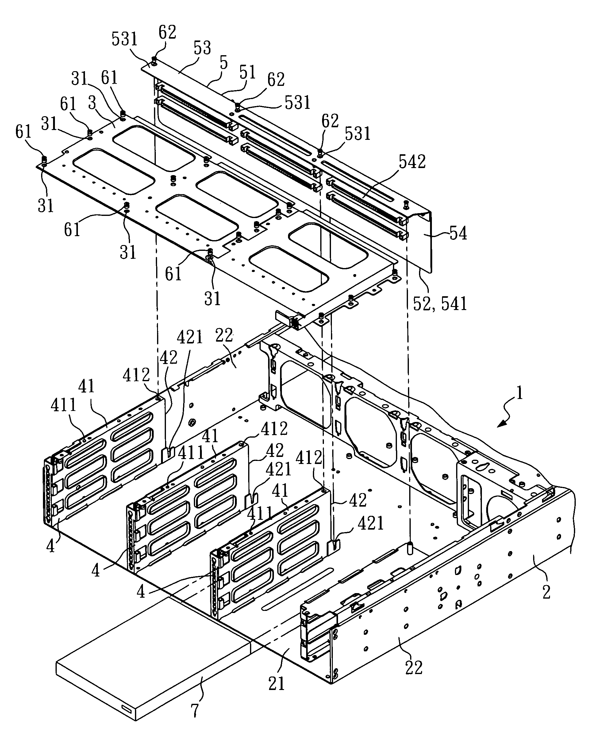
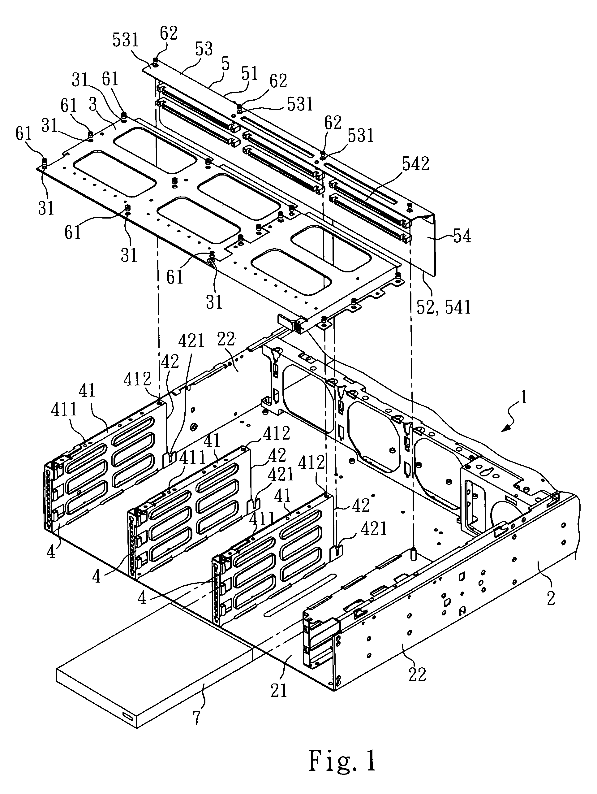
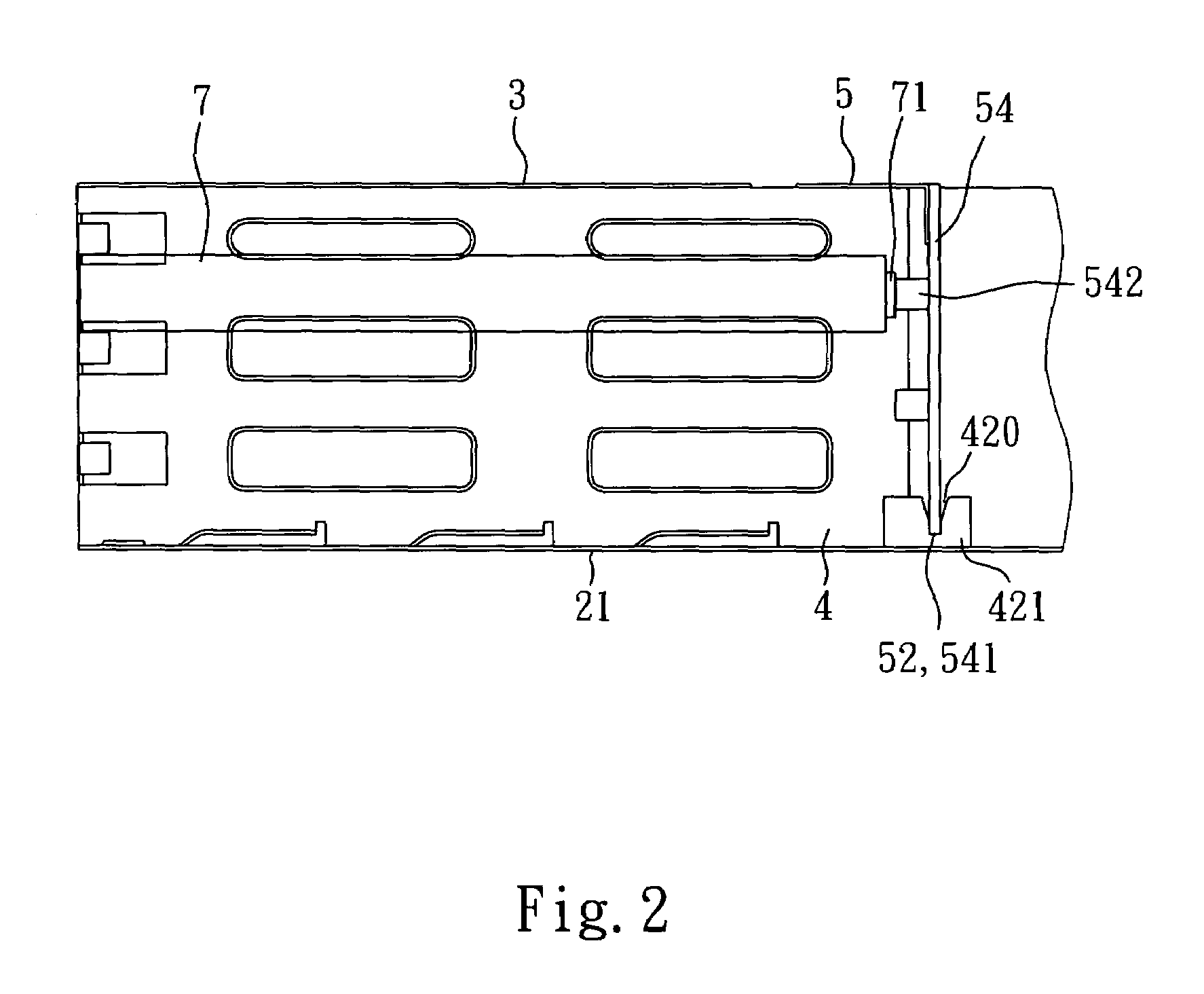
[0012]Referring to FIGS. 1 and 2, a support frame structure is shown mounted inside the housing 2 of a computer system 1. The housing 2 comprises a bottom panel 21, and two side panels 22 perpendicularly upwardly extended from the bottom panel 21 at two opposite longitudinal sides.

[0013]The support frame structure is generally comprised of three upright partition plates 4, a cover plate 3, and an upright back panel 5. The three upright partition plates 4 are respectively perpendicularly mounted on the bottom panel 21 of the housing 2 and extended in longitudinal direction between the two side panels 22. Each upright partition plate 4 comprises a top flange 41, a rear edge 42, a plurality of front mounting devices 411 and a rear mounting device 412 provided at the top flange 41, a locating strip 421 backwardly protruded from the bottom side of the rear edge 42, and an upward locating notch 420 formed in the top side of the locating strip 421. According to the present preferred embodi...


PUM


Abstract

A support frame structure mounted inside the housing of a computer system for supporting electronic drives is disclosed to include a plurality of upright partition plates affixed to the bottom panel between two upright side panels of the housing, a cover plate fastened to the upright side panels of the housing and covered on the upright partition plates, and a detachable upright back panel, which has a bottom side engaged into notched locating strips at the back side of each upright partition plate and a top side terminating in a forwardly extended bend, which is covered on a rear part of the top of each upright partition plate and affixed thereto with a screw.

Description

BACKGROUND OF THE INVENTION[0001]1. Field of the Invention[0002]The present invention relates to a support frame structure and more particularly, to such a support frame structure, which is practical for use in a computer system, for example, a server for supporting HDD (hard disk drives).[0003]2. Description of Related Art[0004]In a computer, more particularly, a server, hard disk drives (HDD) are arranged in an array, and a support frame structure is provided inside the housing of the server to support the HDD in the place. The support frame structure comprises a vertical bracket that accommodates a circuit board, which comprises a plurality of connection ports for the connection of the HDD.[0005]According to the aforesaid conventional design, the vertical bracket is formed integral with the support frame structure. After installation of the support frame structure in the housing of the server, the vertical bracket is kept to suspend inside the housing of the server. When insertin...

Claims


Application Information

Patent Timeline
Patent Type & Authority Patents(United States)
IPC IPC(8): H05K7/14G06F1/16E04D15/00E04F21/00E04G21/14G06F1/18H02B1/01H05K7/18
CPCG06F1/184H05K7/1429G06F1/187
Inventor WU, CHIA-KANGZHAO, ZHENG-JINHSUI, FU-JUNG
Owner TATUNG COMPANY
Why Eureka
Try Eureka