Nanoparticle-enhanced liquid crystal radio frequency phase shifter

a radio frequency phase shifter and nanoparticle technology, applied in the field of phasedarray radio frequency (rf) systems, can solve the problems of limited amount of phase shift produced per applied voltage, and achieve the effects of increasing the amount of phase shift produced, increasing the performance, and increasing the phase shi

a radio frequency phase shifter and nanoparticle technology, applied in the field of phasedarray radio frequency (rf) systems, can solve the problems of limited amount of phase shift produced per applied voltage, and achieve the effects of increasing the amount of phase shift produced, increasing the performance, and increasing the phase shi

US9059496B2Inactive Publication Date: 2015-06-16UNIV OF COLORADO THE REGENTS OF

Image

  • Nanoparticle-enhanced liquid crystal radio frequency phase shifter
  • Nanoparticle-enhanced liquid crystal radio frequency phase shifter
  • Nanoparticle-enhanced liquid crystal radio frequency phase shifter

Examples


Embodiment Construction

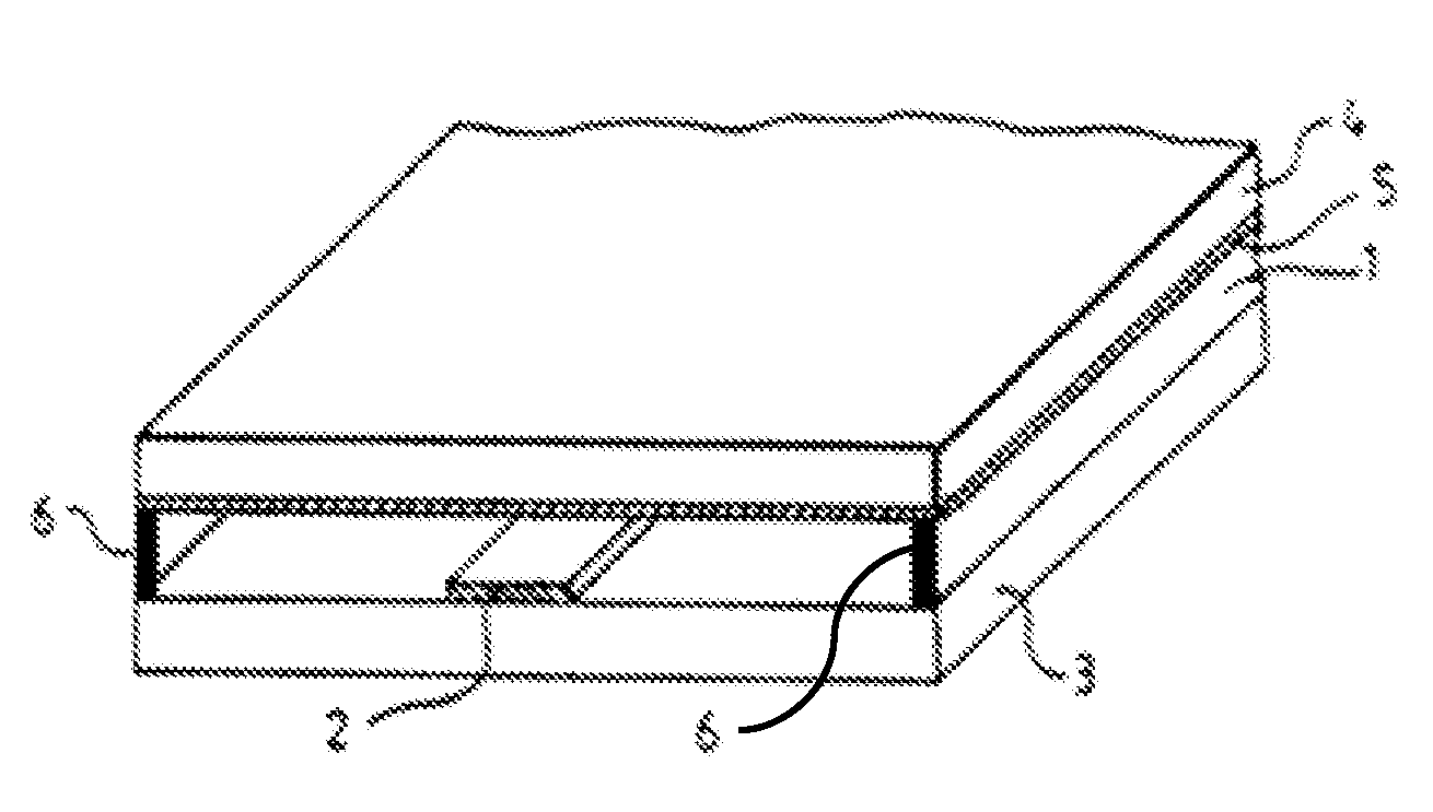
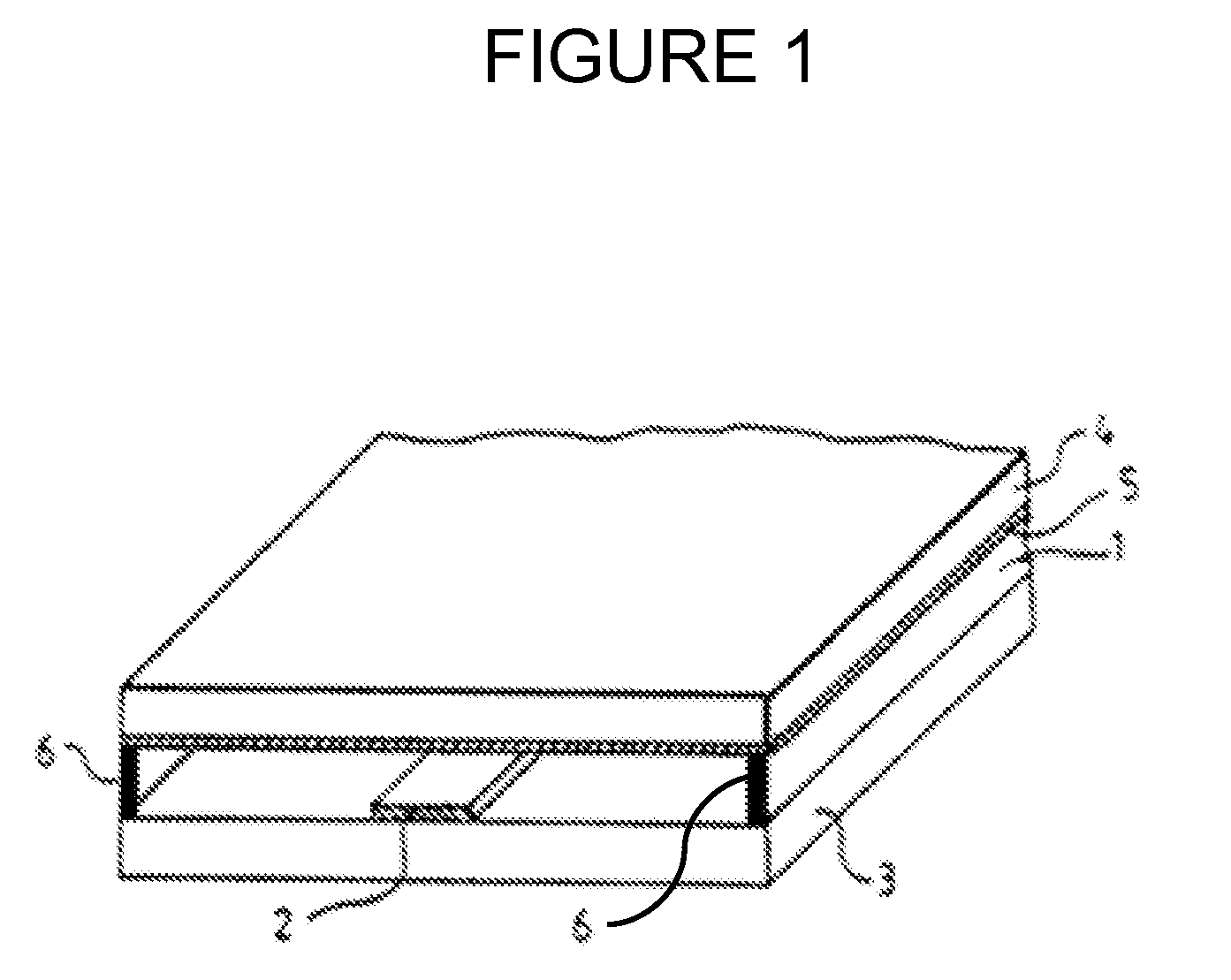
[0012]FIG. 1 illustrates a conventional phase shifter containing an exemplary embodiment of a nanoparticle-enhanced liquid crystal according to the present invention. In this exemplary embodiment, a conventional ā€œinverted microstripā€ configuration is implemented with the present disclosure. Although salient features of the microstrip configuration are provided below, further details of a conventional ā€œinverted microstripā€ configuration are provided in Dolfi et al. (U.S. Pat. No. 5,936,484).

[0013]In FIG. 1, signal line (or electrode) 2 is deposited on a substrate 3, which is made of an insulating material having high permittivity ∈. Suitable materials for signal 2 include, but are not limited to, metals, such as gold, copper, and silver. Furthermore, suitable materials for substrate 3 include, but are not limited to, silicon, magnesium oxide, alumina, GaAs, and glasses of various types.

[0014]Unlike the conventional phase shifter, the liquid crystal layer 1 between substrate signal li...


PUM


Abstract

A nanoparticle-enhanced liquid crystal phase shifter is provided including a first substrate layer, a plurality of electrodes attached to the substrate layer, a ground plane layer attached to a second substrate layer, and a liquid crystal layer between the ground plane layer and the first substrate layer, including a suspension of a liquid crystal material and highly polarizable nanoparticles having specific shape and size characteristics.

Description

GOVERNMENT INTEREST[0001]This invention was made with government support under grant number W911NF-04-1-0247 awarded by the U.S. Army Research Office. The government has certain rights in the invention.FIELD OF THE INVENTION[0002]The present invention relates generally to phased-array radio frequency (RF) systems and, more particularly, to an electronic phase shifter component that may be used in phased-array RF systems.BACKGROUND OF THE INVENTION[0003]Conventional phase shifters are often used in phased-array RF systems to provide controllable phase shift of RF signals. There are various types of phase shifters, including liquid crystal phase shifters. Prior developments in the field of liquid crystal phase shifters are disclosed in Dolfi et al. (U.S. Pat. No. 5,936,484), which is incorporated herein by reference in its entirety. Dolfi et al. discloses a conventional liquid crystal phase shifter that provides a tunable phase shift for use in a phased-array. The conventional phase s...

Claims


Application Information

Patent Timeline
16 Jun 2015
Publication
US9059496B2
IPC
H01P1/18; B82Y20/00; B82Y99/00
CPC
H01P1/18; H01P1/184; B82Y20/00; Y10S977/773; B82Y99/00
Inventors
GLUSHCHENKO, ANATOLIY VOLODYMYROVYCH; CELINSKI, ZBIGNIEW JAN