

Recording apparatus and method of manufacturing recorded matter
a recording apparatus and recording medium technology, applied in typewriters, transfer printing, printing, etc., can solve the problems of affecting the recording medium, the platen device may not sandwich the recording medium having a thickness over a predetermined thickness with the outer frame, and it takes time and effort for a user to remove wrinkles, etc., to achieve the effect of suppressing wrinkles of the recording medium
- Summary
- Abstract
- Description
- Claims
- Application Information
AI Technical Summary
Benefits of technology
Problems solved by technology
Method used
Image

Examples
first embodiment (
FIGS. 1 to 5)
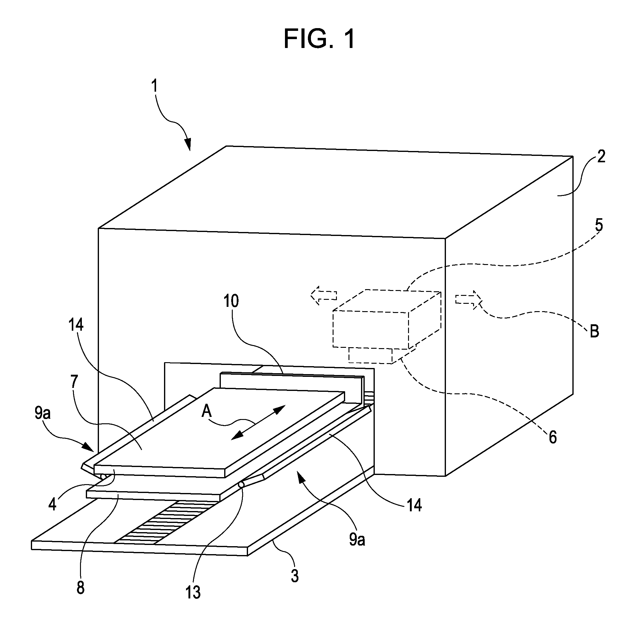
[0057]FIG. 1 is a schematic perspective view of the recording apparatus according to the first embodiment of the invention.
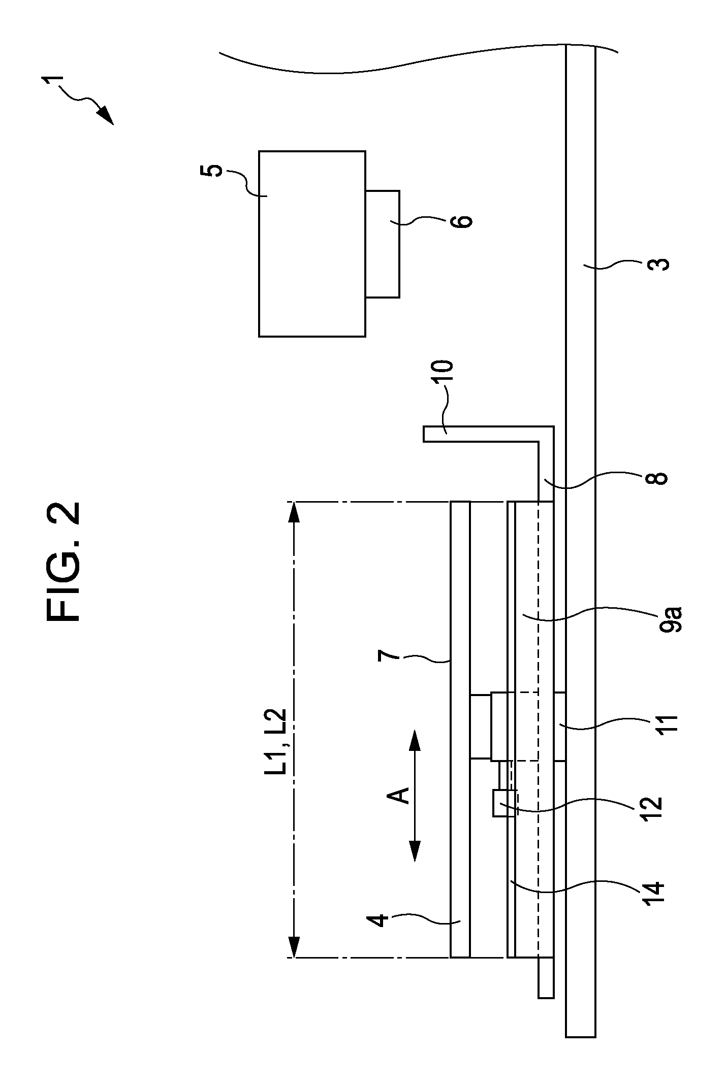
[0058]A recording apparatus 1 of the present embodiment includes a tray 4 having a set surface 7 setting a recording medium P (see, FIG. 3). A transportation section 3, as a moving mechanism, transports the recording medium P by moving the tray 4 in a transportation direction A along the set surface 7. A receiving tray 8 is included and is capable of receiving a protruding portion of the set surface 7 of the recording medium P in the lower portion of the tray 4. The receiving tray 8 has a plate member 10 to hide the inside of the recording apparatus 1.
[0059]In addition, the receiving tray 8 has wing-shaped members 9a on both left and right sides with respect to the transportation direction A. The wing-shaped members 9a are a pulling mechanism capable of applying a force from the set surface 7 of the recording medium P to the protruding portion. The ...
second embodiment (
FIGS. 6A and 6B)
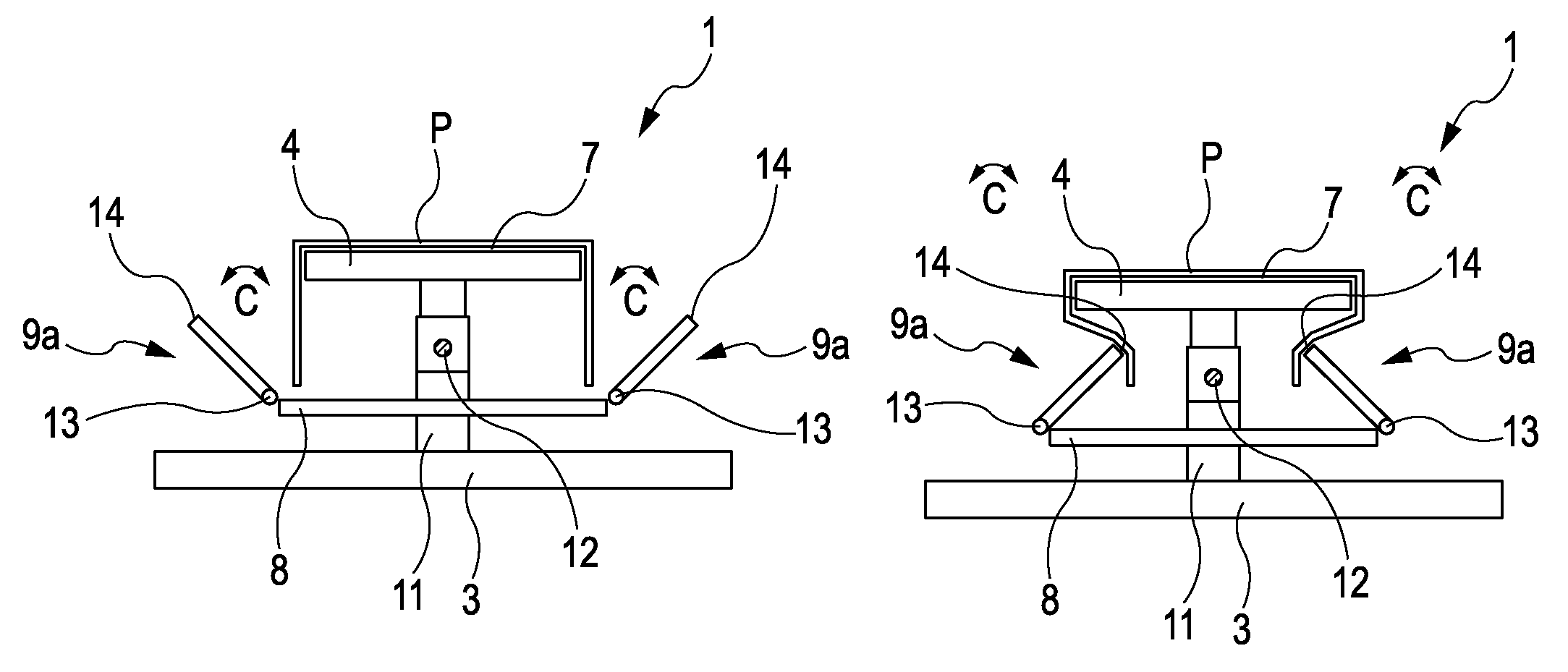
[0074]FIGS. 6A and 6B are schematic front views of the recording apparatus according to the second embodiment of the invention. The same reference numeral will be given to the same configuration member in the first embodiment and repeated description thereof will be omitted.
[0075]FIG. 6A is a view illustrating a state where the wing-shaped members 9b do not apply the force to the protruding portion of the set surface 7 of the recording medium P. FIG. 6B is a view illustrating a state where the wing-shaped members 9b apply the force to the protruding portion of the set surface 7 of the recording medium P.
[0076]The recording apparatus 1 of the embodiment has the wing-shaped members 9b in the both sides of the receiving tray 8, which are the same shapes as the wing-shaped members 9a and the connection section 13 which rotates in a rotation direction C1 without having the free stop function. In addition, the recording apparatus 1 of the embodiment has biasing members con...
fifth embodiments (
Third to Fifth Embodiments (FIGS. 7A to 7C)
[0077]FIGS. 7A to 7C are schematic perspective views of a main portion (the wing-shaped member as the pulling mechanism) of the recording apparatus according to a third to fifth embodiments of the invention. The same reference numeral will be given to the same configuration member in the first embodiment and repeated description thereof will be omitted.
[0078]FIG. 7A is a schematic perspective view of the wing-shaped member 9c according to the third embodiment of the embodiment. The wing-shaped member 9c includes a hinge 15 as a bending section between the connection section 13 and the abutting section 14 about the longitudinal direction (the same direction as the transportation direction A) of the wing-shaped member 9c. Thus, the wing-shaped member 9c is capable of bending in the rotation direction C about the longitudinal direction of the wing-shaped member 9c. In addition, the hinge 15 has the free stop function. Thus, it is possible to s...
PUM
 Abstract
Description
Claims
Application Information