
Connector latch actuator with improved torsional resistance

a technology of latch actuator and latch plate, which is applied in the direction of coupling device connection, coupling parts engagement/disengagement, electrical apparatus, etc., can solve the problems of inducing a torsional shear load upon the tabs, and the straight edge actuator is more susceptible to tearing under torsional load than expected, so as to improve the delatch actuator and resist tearing

Active Publication Date: 2015-07-07
MOLEX INC
View PDF10 Cites 3 Cited by
  • Summary
  • Abstract
  • Description
  • Claims
  • Application Information

AI Technical Summary

Benefits of technology

[0005]Accordingly, there is provided an improved cable assembly that has an improved delatching actuator, or tab that resists tearing when the delatching member is placed under torsion, such as by twisting.
[0008]In accordance with the Present Disclosure, the delatching member has a somewhat elliptical cross-section in that the side edges thereof do not have any right angle aspect, but rather present a rounded edge. The rounded edge may have a diameter equal to that of the thickness of the delatching member or it may be larger to produce a raised, bead-like edge that runs for most of the perimeter of the delatching member. This rounded edge removes the sharp corners previously used and removes the stress risers associated with such sharp sections.

Problems solved by technology

Although these delatching members are intended to be pulled in a longitudinal direction along the axis of the cable associated therewith, many times the installer may turn them during pulling, inducing a torsional shear load upon the tabs.
It has been found that straight edge actuators are more susceptible to tearing under torsional load than expected.

Method used


Image

  • Connector latch actuator with improved torsional resistance
  • Connector latch actuator with improved torsional resistance
  • Connector latch actuator with improved torsional resistance

Examples


Embodiment Construction

[0020]While the Present Disclosure may be susceptible to embodiment in different forms, there is shown in the Figures, and will be described herein in detail, specific embodiments, with the understanding that the disclosure is to be considered an exemplification of the principles of the Present Disclosure, and is not intended to limit the Present Disclosure to that as illustrated.

[0021]In the embodiments illustrated in the Figures, representations of directions such as up, down, left, right, front and rear, used for explaining the structure and movement of the various elements of the Present Disclosure, are not absolute, but relative. These representations are appropriate when the elements are in the position shown in the Figures. If the description of the position of the elements changes, however, these representations are to be changed accordingly.

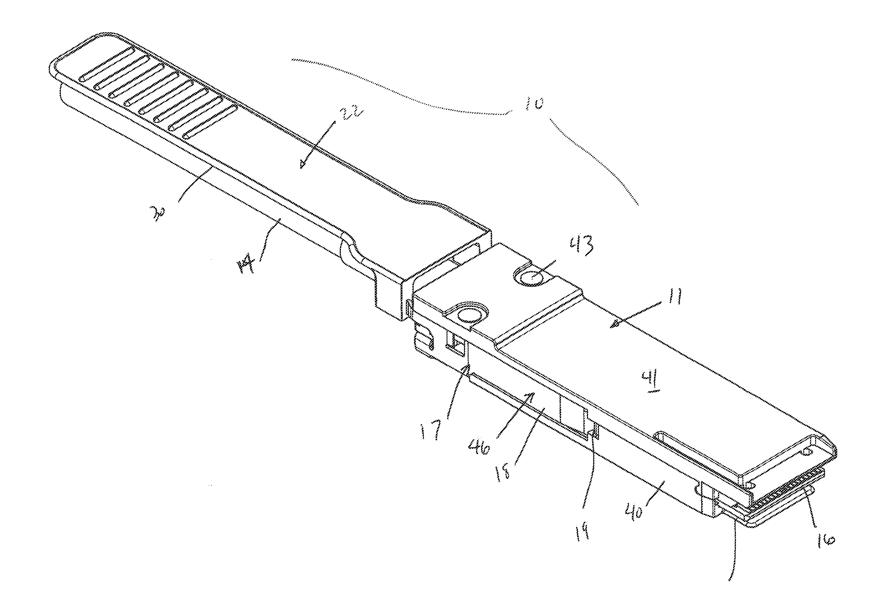
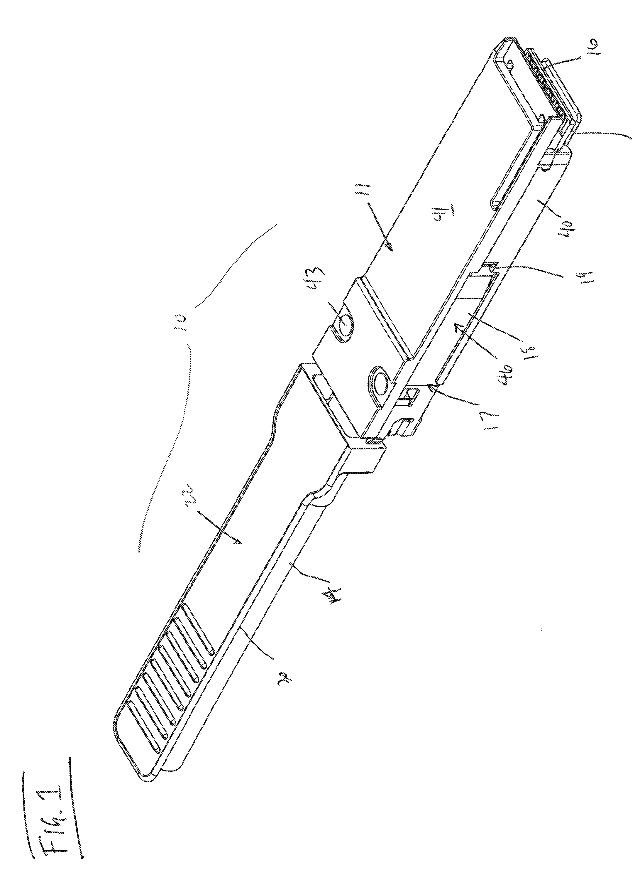
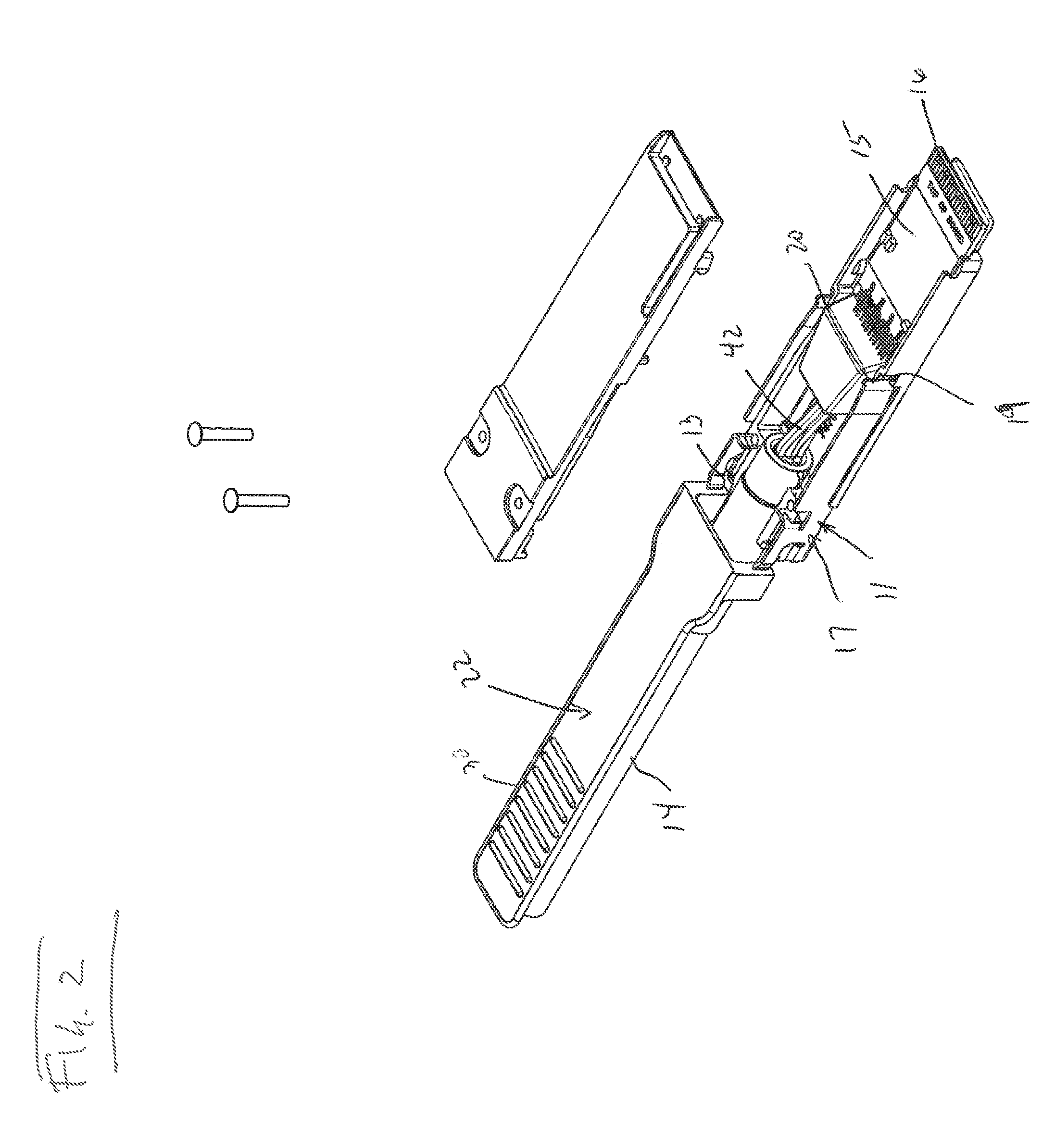
[0022]FIGS. 1-5 illustrate a cable assembly 10 having a protective connector housing 11 with a hollow termination end 13 that receives ...


PUM


Abstract

A cable connector assembly is disclosed for use in connecting electronic devices together. The connector has a housing and a mating blade in the form of a paddle card to which wires of a cable are terminated. The connector housing supports a latching mechanism with an actuator that when selectively pulled delatches the latching mechanism from its engagement with the housing of an electronic device. The actuator has an elongated pull tab portion that has a rounded edge for at least three of its four sides. This rounded edge eliminates the sharp corners associated with rectangular or square cross sections of conventional pull tabs, thereby removing stress riser points and giving the pull tab greater resistance against tearing when subjected to torsional loading.

Description

REFERENCE TO RELATED APPLICATIONS[0001]The Present Disclosure claims priority to prior-filed U.S. Provisional Patent Application No. 61 / 435,656, entitled “Connector Latch Actuator With Improved Torsional Resistance,” filed on 24 Jan. 2011 with the United States Patent And Trademark Office. The content of the aforementioned Patent Application is fully incorporated in its entirety herein.BACKGROUND OF THE PRESENT DISCLOSURE[0002]The Present Disclosure relates generally to cable interconnection systems, and, more particularly, to improved cable connectors for use in high speed data transmission applications.[0003]Conventional cable interconnection systems are often found in electronic devices, such as routers and servers, and are used to form connecting signal transmission lines between multiple devices. Such cable interconnection systems include cable connectors that are terminated to opposing ends of a multiple wire cable. The connectors most commonly utilize an edge card as a connec...

Claims


Application Information

Patent Timeline
Patent Type & Authority Patents(United States)
IPC IPC(8): H01R13/62H01R13/627H01R13/66
CPCH01R13/6275H01R13/6658
Inventor LLOYD, BRIAN KEITHBYCZKIEWICZ, BARBARA
Owner MOLEX INC
Learn More