Card reader and control method therefor

a card reader and control method technology, applied in the field of card readers, can solve the problems of difficult to acquire significant magnetic data, so-called “skimming” has been conventionally a serious problem, and the user cannot prevent skimming at the time of taking out a card, so as to prevent significant magnetic data, the user cannot take out the card with force, and the effect of significant magnetic data

Active Publication Date: 2015-07-14
SANKYO SEIKI MFG CO LTD
View PDF6 Cites 0 Cited by
  • Summary
  • Abstract
  • Description
  • Claims
  • Application Information

AI Technical Summary

Benefits of technology

[0007]In view of the problem described above, at least an embodiment of the present invention may provide a card reader which is capable of preventing skimming when a card is taken out from the card reader by a user. Further, at least an embodiment the present invention may also provide a control method for a card reader which is capable of preventing skimming when a card is taken out from the card reader by a user.

Problems solved by technology

In the financial institutions in which the card reader is utilized, a so-called “skimming” has been conventionally a serious problem.
Accordingly, in the card reader, even when a skimming magnetic head is attached to an insertion portion for a card, it is difficult that significant magnetic data are acquired by using the skimming magnetic head at the time of a taking-in operation of a card and an ejecting operation of the card.
However, in the card reader, when a skimming magnetic head is attached to an inserting portion for a card, skimming at the time of taking-out of a card by a user cannot be prevented.

Method used


Image

  • Card reader and control method therefor
  • Card reader and control method therefor
  • Card reader and control method therefor

Examples


Embodiment Construction

[0020]An embodiment of the present invention will be described below with reference to the accompanying drawings.

[0021](Structure of Card Reader)

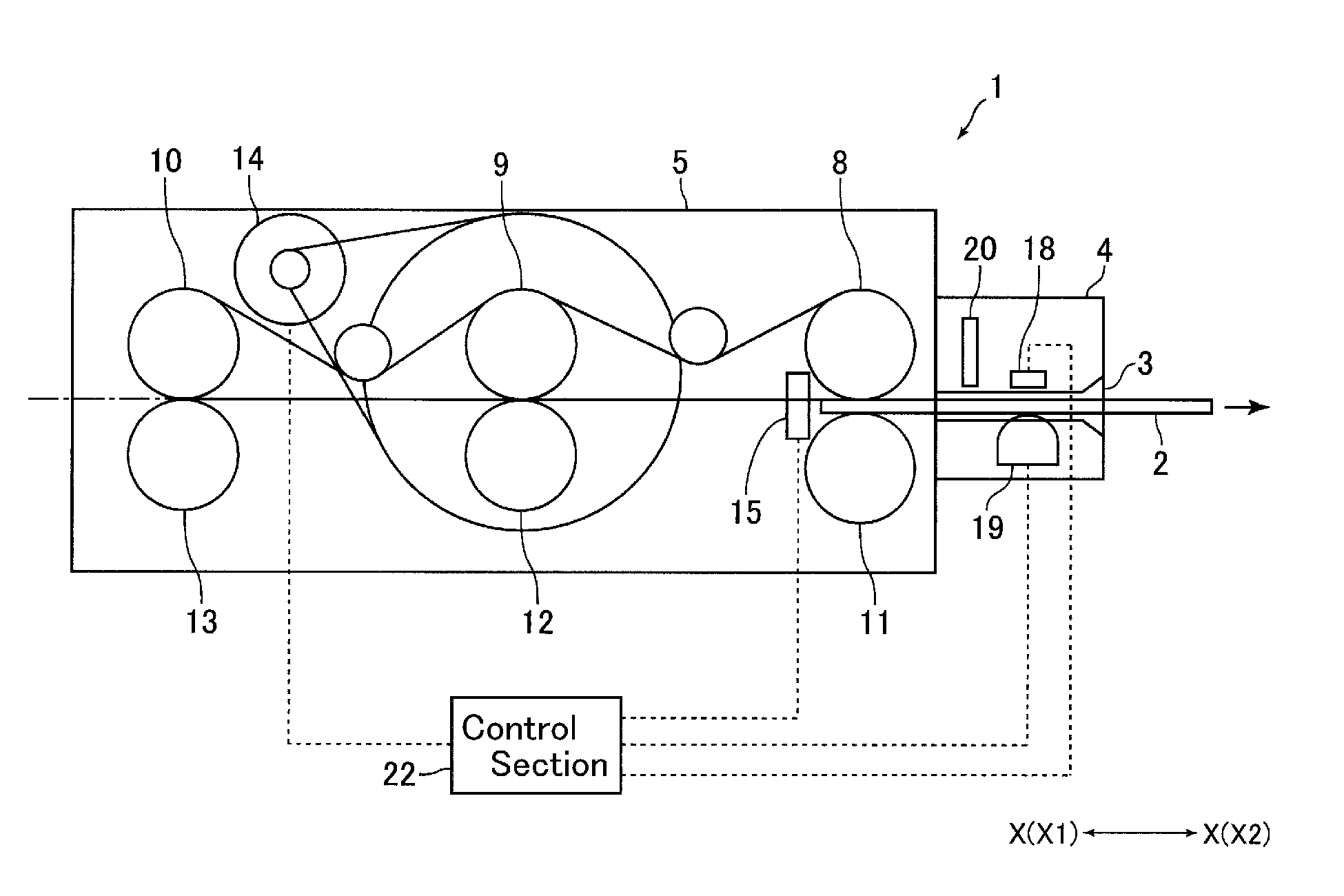
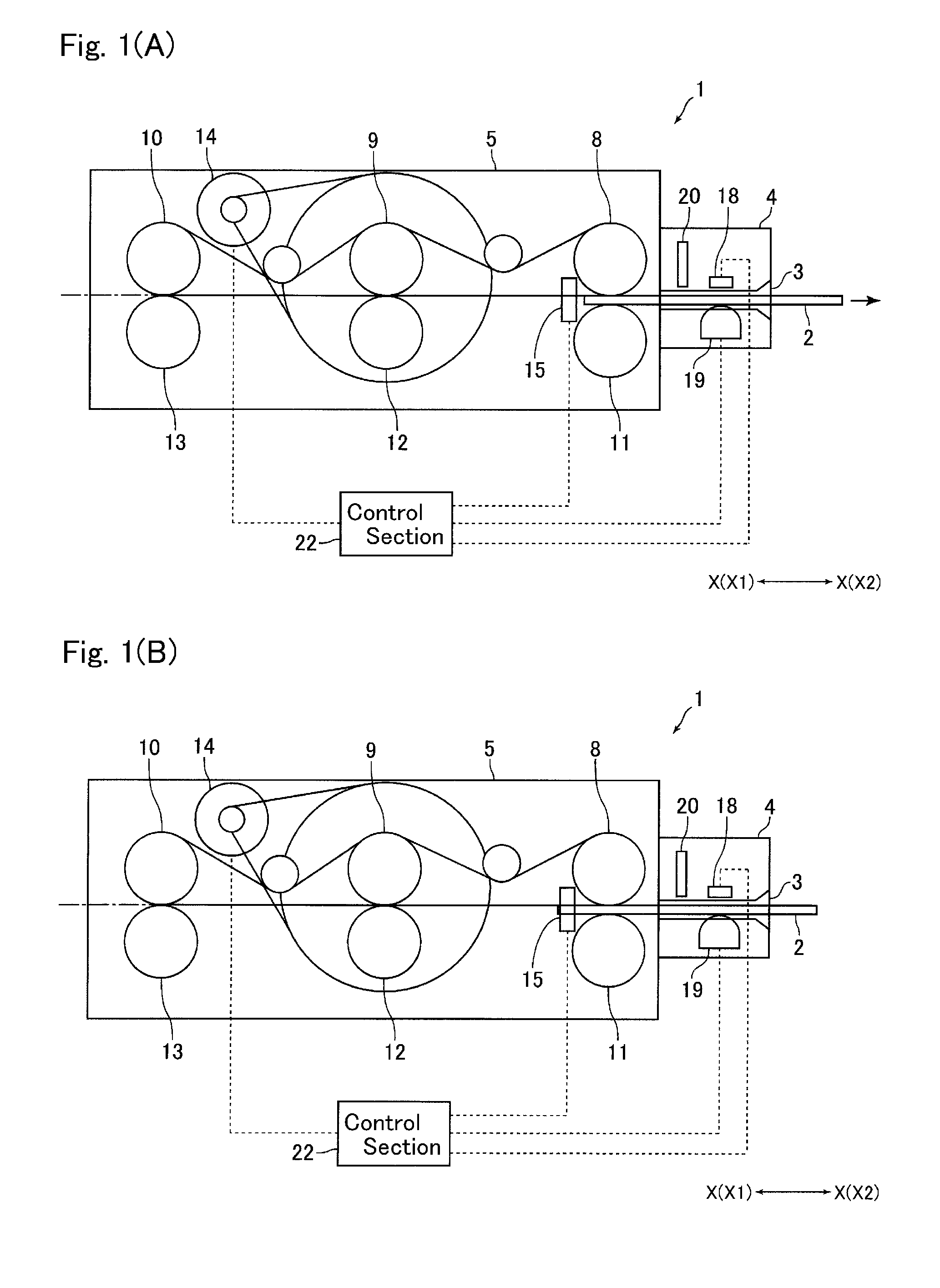
[0022]FIGS. 1(A) and 1(B) are explanatory side views showing a schematic structure of a card reader 1 in accordance with an embodiment of the present invention. FIG. 1(A) is a side view showing a taking-out ready state that a card 2 is capable of being taken out from the card reader 1 by a user, and FIG. 1(B) is a side view showing a state that a card 2 is detected by a card sensor 15.

[0023]A card reader 1 in this embodiment is a device which is structured to perform reading of magnetic data recorded on a card 2 and / or recording of magnetic data on a card 2. The card reader 1 is mounted and used in a predetermined host apparatus such as an ATM (Automated Teller Machine). The card reader 1 includes, as shown in FIGS. 1(A) and 1(B), a card insertion-and-ejection part 4 in which a card insertion-and-ejection port 3 into which a card 2 is inser...


PUM


Abstract

A card reader includes a taking-out detection mechanism for detecting taking-out of a card from a taking-out ready state, which is a state that a part of the card is protruded from the card insertion-and-ejection port to an outer side of the card reader so that the card is capable of being taken out from the card reader, and a resistance applying mechanism structured to abut with the card taken out from the card reader to apply a frictional resistance to the card so as to disturb taking-out of the card. The resistance applying mechanism may include a feed roller configured to feed the card in a direction ejecting the card from an inside of the card reader until the taking-out ready state and, when start of taking-out of the card from the taking-out ready state is detected by the taking-out detection mechanism, the feed roller may be temporarily rotated in a direction taking the card into the card reader.

Description

[0001]Priority under 35 U.S.C. §119(a) is claimed from Japanese Application No. 2012-151268, filed Jul. 5, 2012, the disclosure of which is also incorporated herein by reference.FIELD OF THE INVENTION[0002]The present invention relates to a card reader which is structured to read magnetic data recorded on a card and / or record magnetic data on a card. Further, the present invention relates to a control method for the card reader.BACKGROUND OF THE INVENTION[0003]Conventionally, a card reader structured to read magnetic data on a card and / or record magnetic data on a card has been widely utilized. The card reader is, for example, mounted on an automatic teller machine which is installed in a financial institution or the like. In the financial institutions in which the card reader is utilized, a so-called “skimming” has been conventionally a serious problem. In skimming, a criminal attaches a magnetic head to an inserting portion for a card of an automatic teller machine to illegally ac...

Claims


Application Information

Patent Timeline
Patent Type & Authority Patents(United States)
IPC IPC(8): G06K7/08G06K7/00G06K13/08G06K13/26G06K19/00
CPCG06K7/00G06K7/082G06K7/084G06K13/08G06K13/26G06K19/005
Inventor KITAZAWA, YASUHIRO
Owner SANKYO SEIKI MFG CO LTD
Why Eureka
Try Eureka