Ventilation system with controllable air input and output

a technology of controllable air and ventilation system, which is applied in ventilation system, lighting and heating apparatus, heating types, etc., can solve the problem that the ventilation system b>9/b> is not equipped with any device that can stop the air circulation, and achieve the effect of preventing fire from spreading

Inactive Publication Date: 2015-07-21
NAT PINGTUNG UNIV OF SCI & TECH
View PDF64 Cites 8 Cited by
  • Summary
  • Abstract
  • Description
  • Claims
  • Application Information

AI Technical Summary

Benefits of technology

[0007]It is therefore the primary objective of this invention to provide a ventilation system with controllable air input and output which can stop external air from entering the ventilation system. Thus, fire can be prevented from spreading.
[0008]It is another objective of this invention to provide a ventilation system with controllable air input and output which can allow more heat to be expelled when a fire accident takes place, thereby speeding up the heat expelled.

Problems solved by technology

However, the ventilation system 9 is not equipped with any device that can stop its air circulation when it is desired.

Method used


Image

  • Ventilation system with controllable air input and output
  • Ventilation system with controllable air input and output
  • Ventilation system with controllable air input and output

Examples


Embodiment Construction

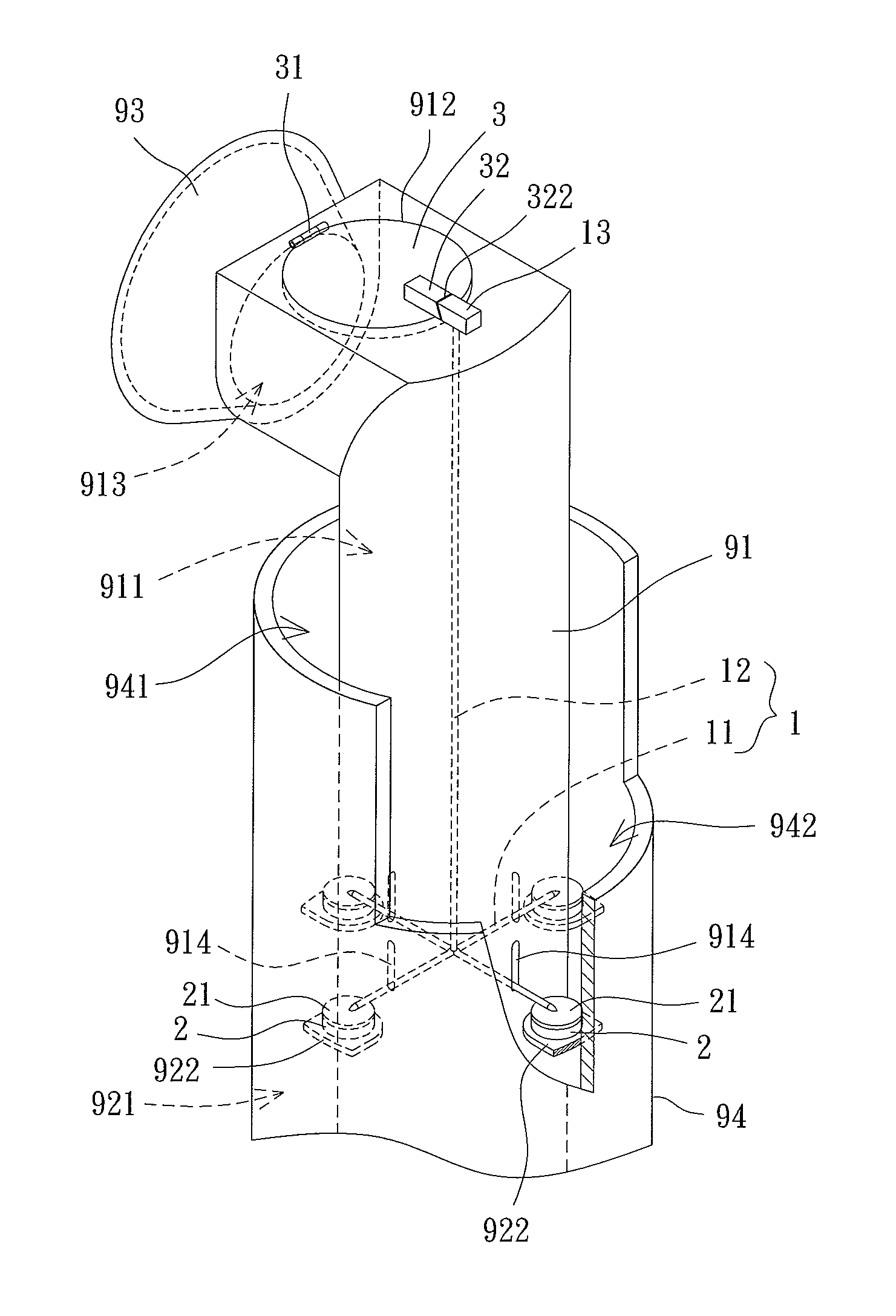
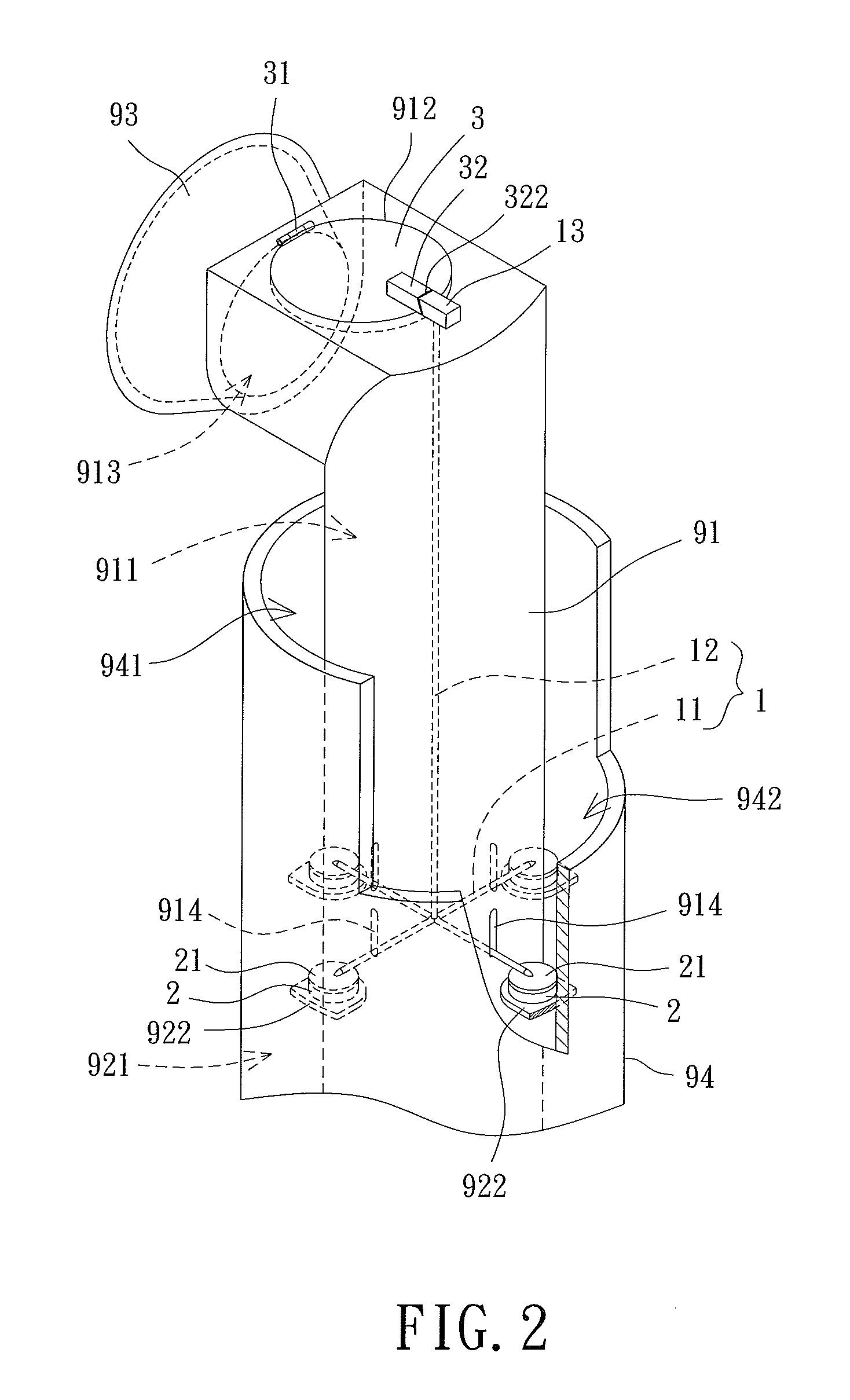
[0018]Referring to FIG. 2, the ventilation system 9 equipped with an air intake and exhaust apparatus for regulating ventilation of the ventilation system 9 is shown according to a preferred embodiment of the invention. The air intake and exhaust apparatus comprises an elevating member 1, a plurality of driving members 2 and a cover plate 3. The air intake and exhaust apparatus is installed in the ventilation system 9.

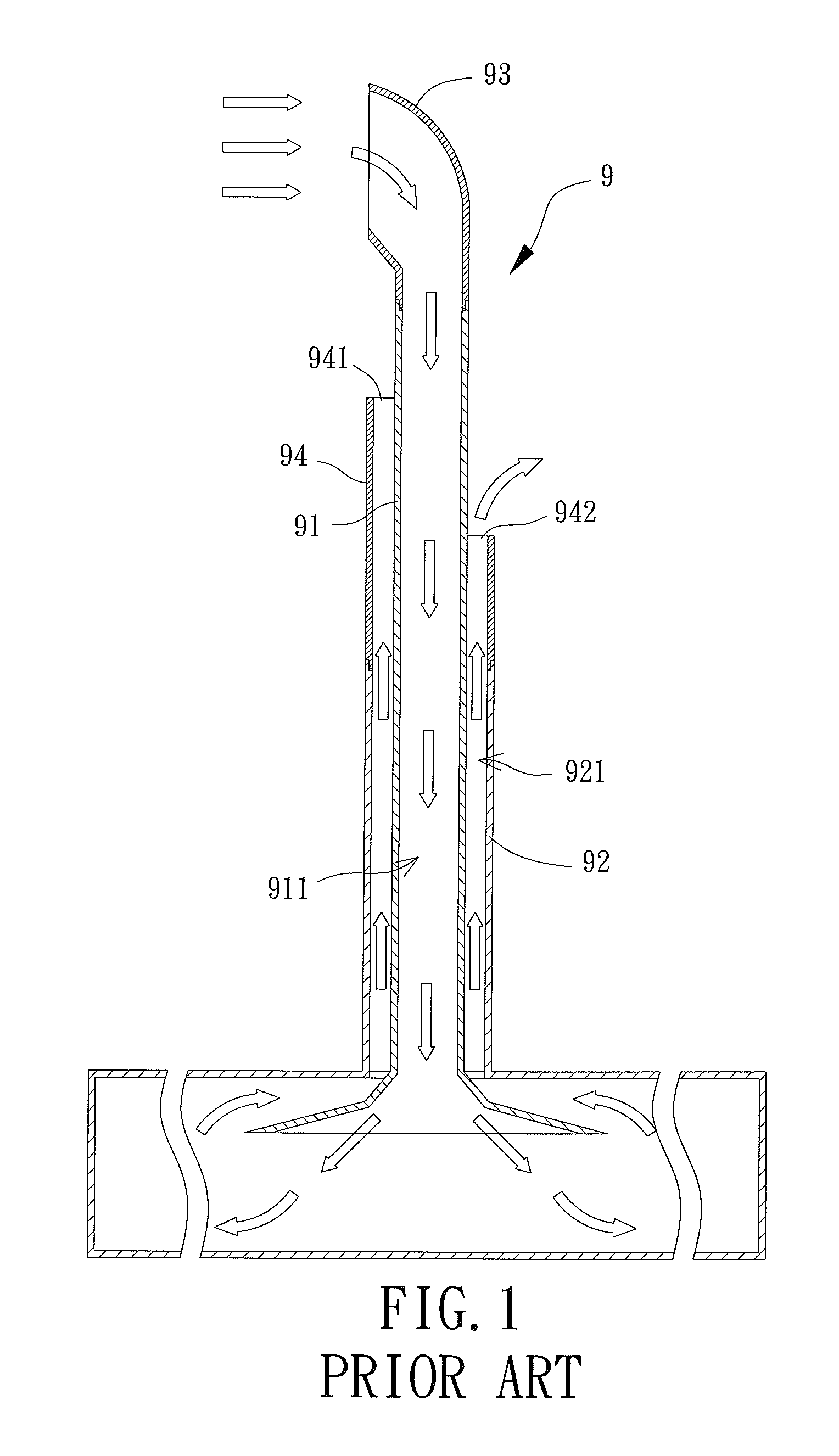
[0019]The ventilation system 9 comprises an inner tube 91 and an outer tube 92 coaxial with the inner tube 91, as shown in FIG. 4. The inner tube 91 has an intake air channel 911, and an exhaust channel 921 is formed between the inner tube 91 and the outer tube 92. The inner tube 91 has one end extending in a radial direction. The inner tube 91 further comprises an air outlet 912 on a top face thereof, as well as an air inlet 913 at the end of the inner tube 91 extending in the radial direction. Note both the air outlet 912 and the air inlet 913 are formed on the same ...


PUM


Abstract

The invention discloses a ventilation system including an inner, an outer tube and an air intake and exhaust apparatus. The inner tube has one end extending in a radial direction, wherein an air outlet and an air outlet are formed on the inner tube. An exhaust channel is formed between the inner and outer tubes, and the supporting member is disposed in the exhaust channel. The air intake and exhaust apparatus comprises an elevating member, a plurality of driving members and a cover plate. The elevating member has a connection block. The driving members are made of expandable material. The cover plate is rotatably coupled with the inner tube and has a connection portion. The connection portion abuts against the connection block when the driving members are not expanding. The connection portion of the cover plate disengages from the connection block when the driving members are expanding.

Description

BACKGROUND OF THE INVENTION[0001]1. Field of the Invention[0002]The present invention generally relates to a ventilation system with controllable air input and output and, more particularly, to a ventilation system with controllable air input and output that is installed in a building to control ventilation of the building.[0003]2. Description of the Related Art[0004]Referring to FIG. 1, a conventional tube-type air intake and exhaust structure is shown. The air intake and exhaust structure comprises a ventilation system 9 having an inner tube 91 and an outer tube 92 coaxial with the inner tube 91. The inner tube 91 has an intake air channel 911, and an exhaust channel 921 is formed between the inner tube 91 and the outer tube 92. The inner tube 91 has an air-guiding cover 93 at one end thereof for collecting airflows.[0005]The ventilation system 9 further comprises an extra outer tube 94 on a top of the outer tube 92. The outer tube 94 has a windward opening 941 and an air-guiding ...

Claims


Application Information

Patent Timeline
Patent Type & Authority Patents(United States)
IPC IPC(8): F24F11/02F24F11/053F24F7/04F24F11/00F24F11/76
CPCF24F7/04F24F11/053F24F2011/0098F24F11/35F24F11/76
Inventor TAI, CHANG-HSIENMIAO, JR-MINGLO, SHI-WEITENG, JYH-TONG
Owner NAT PINGTUNG UNIV OF SCI & TECH
Why Eureka
Try Eureka