Pattern recognition method and pattern recognition apparatus

a recognition method and pattern technology, applied in the field of pattern recognition methods and pattern recognition apparatuses, can solve the problems of increasing processing costs, difficulty in realizing robust face recognition algorithms for variations, and affecting recognition accuracy, so as to prevent the reduction of recognition accuracy and increase processing costs

Active Publication Date: 2015-07-28
CANON KK
View PDF43 Cites 2 Cited by
  • Summary
  • Abstract
  • Description
  • Claims
  • Application Information

AI Technical Summary

Benefits of technology

[0008]The present invention has been made in view of the foregoing problems, and an embodiment of the present invention provides a pattern recognition method and a pattern recognition apparatus for preventing the reduction of recognition accuracy caused by variations in illumination, face orientation, expression, etc. and controlling the increase of processing cost.

Problems solved by technology

Therefore, the realization of a robust face recognition algorithm for the variations is difficult.
However, the inverse transform process of Document 1 may delete feature quantities indicating individual differences, and the recognition accuracy may be affected.
The execution of an inverse transformation process for removing all predicted variation factors from the input image increases the processing cost.

Method used


Image

  • Pattern recognition method and pattern recognition apparatus
  • Pattern recognition method and pattern recognition apparatus
  • Pattern recognition method and pattern recognition apparatus

Examples


first embodiment

Pattern Recognition Apparatus

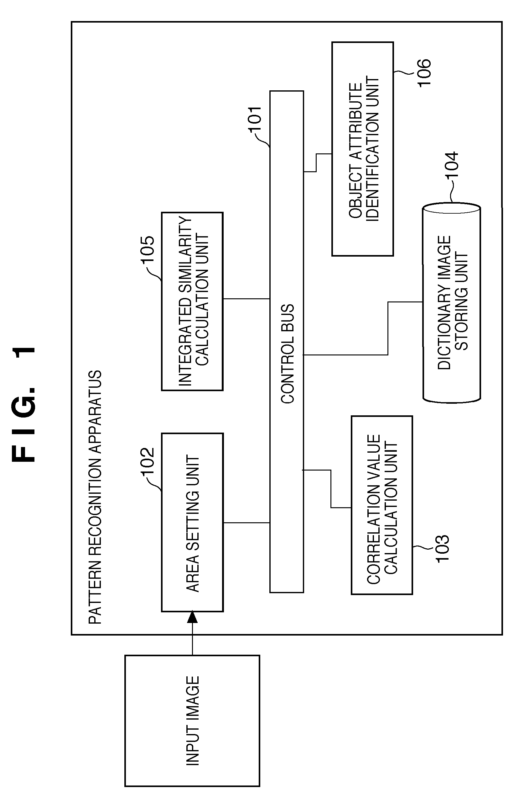
[0027]FIG. 1 is a functional block diagram of a pattern recognition apparatus. Hereinafter, details of the blocks will be described. A control bus 101 controls input and output of the functional blocks. An area setting unit 102 acquires an input image inputted from the outside and sets a local area for extracting a feature quantity of the acquired input image. Details of a method of setting the local area, etc., will be described later. A general method can be used as the method of acquiring the image. For example, an imaging element such as a CCD may be incorporated into a pattern recognition apparatus, and the image may be acquired through the imaging element. A correlation value calculation unit 103 calculates correlation values between the input image and dictionary images acquired in advance for each local area set by the area setting unit 102. Details of the correlation value calculation method in the correlation value calculation unit 103 will be ...

second embodiment

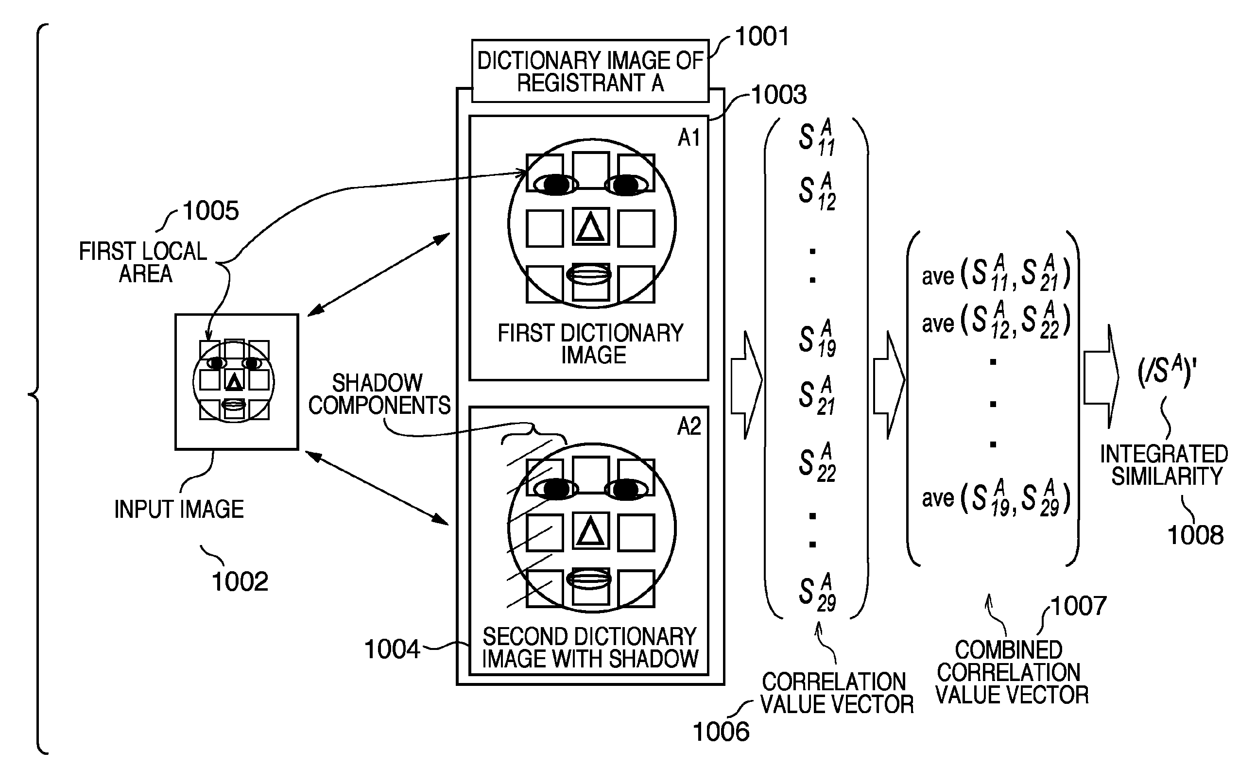
[0048]A second embodiment will be described. The basic flow of the second embodiment is substantially the same as the first embodiment, and the calculation method in the integrated similarity calculation process (S203) is different. The calculation method of the integrated similarity of the second embodiment will be described with reference to a conceptual diagram of FIG. 10 and a processing flow chart of FIG. 11.

[0049]Dictionary images 1001 of the registrant A of FIG. 10 denote dictionary images related to the registrant A, and it is assumed that there are two dictionary images in FIG. 10. Although there is one registrant in FIG. 10, there may be persons other than the registrant A. In that case, the same process as shown in FIG. 10 is applied to the registered images other than the registrant A. As described, three or more dictionary images may be registered for one registrant. In the present embodiment, the dictionary images 1001 of the registrant A include a first dictionary ima...

third embodiment

[0061]A third embodiment will be described. The basic flow of the third embodiment is substantially the same as the first embodiment. The difference is that the local area used to calculate the integrated similarity is dynamically changed based on the difference in visibility between the input image and the registered images. Details of the third embodiment will be described with reference to FIGS. 12, 13, and 14A to 14D.

[0062]FIG. 12 is a conceptual diagram showing a summary of the third embodiment, and FIG. 13 is a processing flow chart showing details of the process. The summary of the present embodiment will be described with reference to FIG. 12. Dictionary images 1201 of the registrant A of FIG. 12 denote dictionary images related to the registrant A, and it is assumed that there are two dictionary images in FIG. 12. Although there is one registrant in FIG. 12, there may be persons other than the registrant A. In that case, the same process as shown in FIG. 12 is applied to th...


PUM


Abstract

A pattern recognition apparatus that recognizes a data attribute of input data calculates correlation values of feature quantities of corresponding local patterns between the input data and dictionary data for each of a plurality of dictionary data prepared for each data attribute, combines, for each data attribute, the calculated correlation values of local patterns of each dictionary datum to acquire a set of correlation values of each data attribute, integrates correlation values included in each set of correlation values of each data attribute to calculate a similarity of the input data for each data attribute, and identifies the data attribute of the input data based on the calculated similarity.

Description

BACKGROUND OF THE INVENTION[0001]1. Field of the Invention[0002]The present invention relates to a pattern recognition method and a pattern recognition apparatus for recognizing a specific pattern such as a face and a person.[0003]2. Description of the Related Art[0004]There is a pattern recognition technique for detecting and identifying a predetermined pattern from an input pattern. Pattern recognition technique has progressed alongside performance increases in computers, and recently a system of detecting a face in an image in real time has started to come out. There is also a known face recognition technique that detects a face area in an image and verifying whom the person in the face area is. The accuracy of the face recognition technique is significantly affected by illumination conditions, such as oblique light, as well as face orientation variations, expression variations, and occlusions. The variations are not independent from each other. Therefore, the realization of a ro...

Claims


Application Information

Patent Timeline
Patent Type & Authority Patents(United States)
IPC IPC(8): G06K9/46G06K9/00
CPCG06K9/00288G06K9/00281G06V40/171G06V40/172
Inventor SUZUKI, TAKASHIMORI, KATSUHIKOSATO, HIROSHI
Owner CANON KK
Why Eureka
Try Eureka