Image processing apparatus

a technology of image processing and apparatus, applied in the field of image processing apparatus, can solve the problems of high calculation cost and likely deterioration of the accuracy of recognizing the surrounding vehicle, and achieve the effect of reducing the calculation amount and reducing the calculation cos

Active Publication Date: 2020-01-23
TOYOTA JIDOSHA KK +1
View PDF0 Cites 0 Cited by
  • Summary
  • Abstract
  • Description
  • Claims
  • Application Information

AI Technical Summary

Benefits of technology

[0005]The image processing apparatus disclosed in the Patent Literature 2 execute the predetermined processing on each of two images captured by two cameras, respectively. Thus, if the vehicle disclosed in the Patent Literature 1 has two cameras (alternatively, a plurality of cameras), the processing for recognizing the condition of the surrounding vehicle such as the position, the velocity and the acceleration rate is executed on each of a plurality of images captured by the plurality of cameras, respectively. However, in this case, there is a possibility that a calculation cost (in other words, a calculation load) of the image processing apparatus becomes high (in other words, a calculation amount balloons). Thus, it is desired to reduce the calculation cost (namely, reduce the calculation amount).

Problems solved by technology

However, in this case, there is a possibility that a calculation cost (in other words, a calculation load) of the image processing apparatus becomes high (in other words, a calculation amount balloons).
However, each of these methods likely deteriorates an accuracy of recognizing the surrounding vehicle (alternatively, any target) in the image.

Method used


Image

  • Image processing apparatus
  • Image processing apparatus
  • Image processing apparatus

Examples


Embodiment Construction

[0021]Hereinafter, with reference to drawings, one embodiment of the image processing apparatus of the present invention will be described. In the following description, a vehicle 1 to which one embodiment of the image processing apparatus of the present invention is adapted will be described.

(1) Structure of Vehicle 1

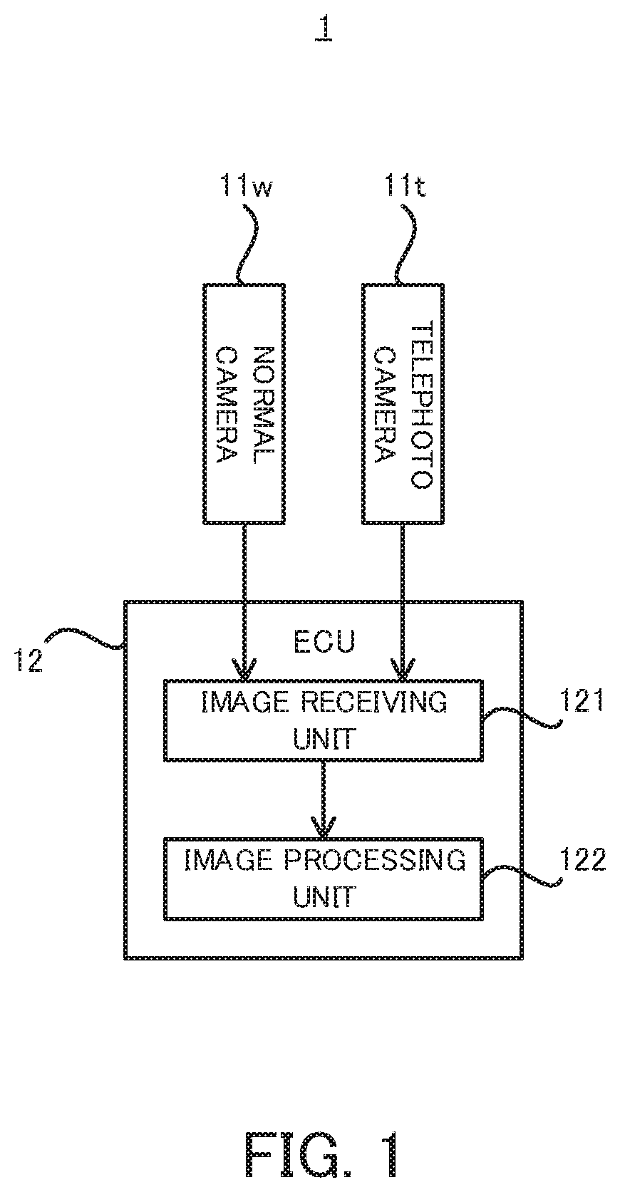
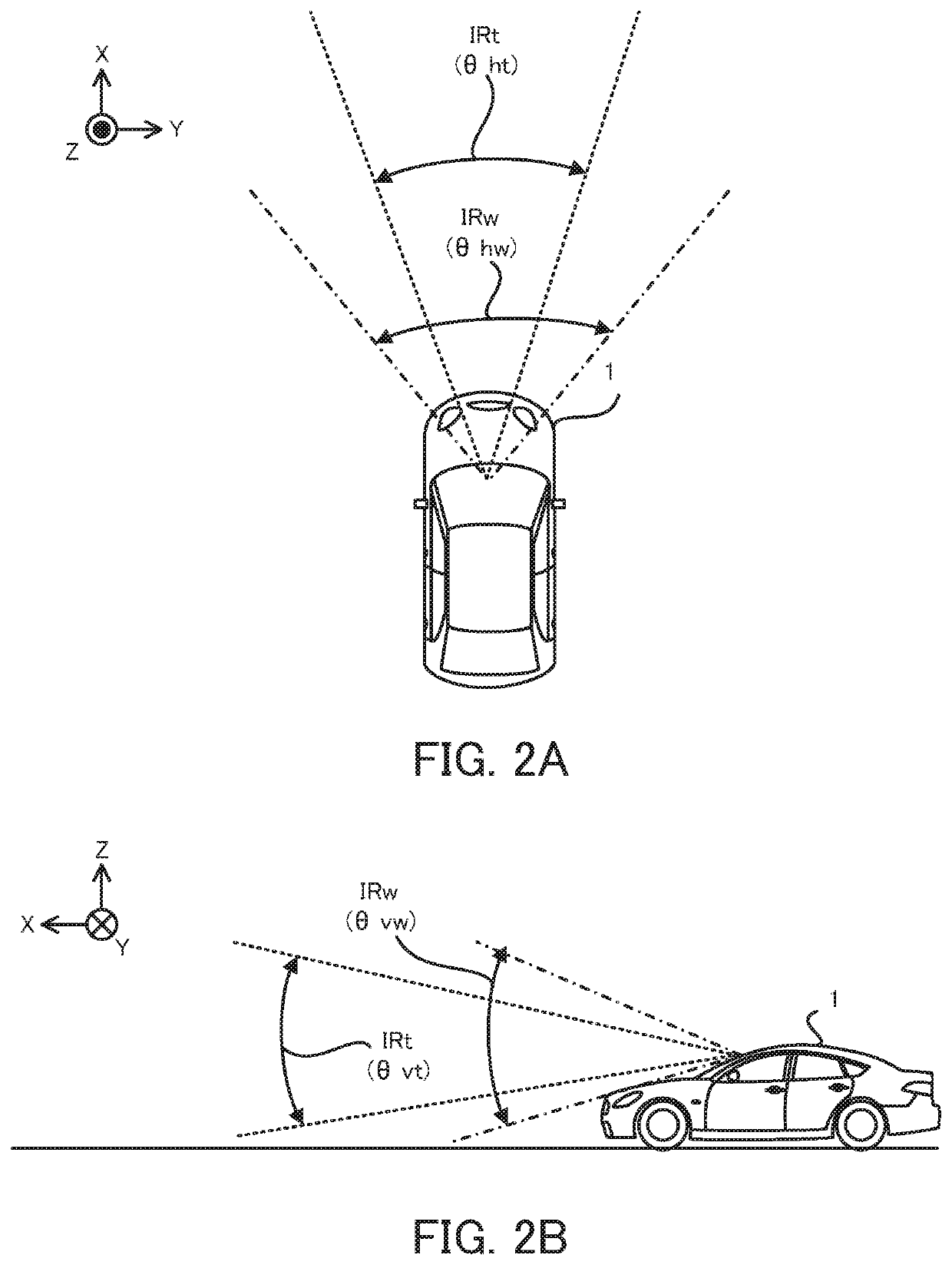
[0022]Firstly, with reference to FIG. 1 and FIG. 2A to FIG. 2B, a structure of the vehicle 1 in the present embodiment will be explained. FIG. 1 is a block diagram that illustrates the structure of the vehicle 1 in a present embodiment. FIG. 2A is a planer view that illustrates an imaging range IRw of a normal camera 11w and an imaging range IRt of a telephoto camera 11t in the vehicle 1 in the present embodiment and FIG. 2A is a cross-sectional view that illustrates the imaging range IRw of the normal camera 11w and the imaging range IRt of the telephoto camera 11t in the vehicle 1 in the present embodiment. Incidentally, in the below described description, the embodi...


PUM


Abstract

An image processing apparatus (12) has a processing device (122) for executing, on a first image (111w) captured by a first imaging device (11w) imaging a first imaging area and a second image (111t) captured by a second imaging device (11t) imaging a second imaging area, an image recognition processing for recognizing a target in the first image and the second image, the processing device executes the image recognition processing on a non-overlapped image part (113w) of the first image without executing it on a overlapped image part (112w) of the first image when the processing device executes the image recognition processing on the first image, the non-overlapped image part includes a non-overlapped area at which the first imaging area does not overlap with the second imaging area, the overlapped image part includes a overlapped area at which the first imaging area overlaps with the second imaging area.

Description

TECHNICAL FIELD[0001]The present invention relates to a technical field of an image processing apparatus that is configured to execute an image recognition processing for recognizing a target in an image captured by an imaging device such as a camera, for example.BACKGROUND ART[0002]A Patent Literature 1 discloses, as one example of an image processing apparatus, an image processing apparatus that is used by a vehicle having a camera and that is configured to recognize a condition of a surrounding vehicle such as a position, a velocity and an acceleration rate on the basis of an information inputted from the camera.[0003]There is a Patent Literature 2 as another document relating to the present invention. The Patent Literature 2 discloses an image processing apparatus that is used by a vehicle having a camera including a wide angle lens and a camera including a telephoto lens and that is configured to execute a predetermined processing on each of two images captured by these two cam...

Claims


Application Information

Patent Timeline
Patent Type & Authority Applications(United States)
IPC IPC(8): G06K9/00B60R11/04G06T7/11G06T7/174G06T5/50G06V10/147
CPCB60R11/04B60R2300/303B60R2300/8093G06T5/50G06T7/174G06T7/11B60R2300/302G06K9/00805G06T2207/20221B60R2300/105G06T2207/30261G06V20/10G06V20/56G06V20/58G06V10/147
Inventor YOKOTA, MASATAKASUN, JIASOTA, TAKAHIRO
Owner TOYOTA JIDOSHA KK
Why Eureka
Try Eureka