
Disparity estimation method of stereoscopic image

a stereoscopic image and dispersion estimation technology, applied in image analysis, image enhancement, instruments, etc., can solve problems such as heavy burden, and achieve the effects of reducing computation amount, reducing computation time of disparity optimization, and improving matching disparities

Active Publication Date: 2015-08-11
ACER INC
View PDF4 Cites 2 Cited by
  • Summary
  • Abstract
  • Description
  • Claims
  • Application Information

AI Technical Summary

Benefits of technology

[0008]The present disclosure provides a disparity estimation method of stereoscopic images capable of reducing computation times of disparity optimization and obtaining better matching disparities so as to dramatically reduce computation amount.
[0009]The present disclosure further provides a disparity estimation method of stereoscopic images capable of reducing the usage of memory buffers by improving a scan order.
[0012]To sum up, by the disparity estimation method of stereoscopic images of the present disclosure, computation times of disparity optimization may be reduced, and better matching disparities may be obtained so as to dramatically reduce the computation amount. In addition, the usage of the memory buffers may be reduced as the scan order is improved.

Problems solved by technology

However, since the aggregated cost value is quite large, not only a large amount of computations have to be executed, but also a large amount of memory spaces is needed, which lead to a heavy burden when the real-time processing is required by the conventional technology.

Method used


Image

  • Disparity estimation method of stereoscopic image
  • Disparity estimation method of stereoscopic image
  • Disparity estimation method of stereoscopic image

Examples


first embodiment

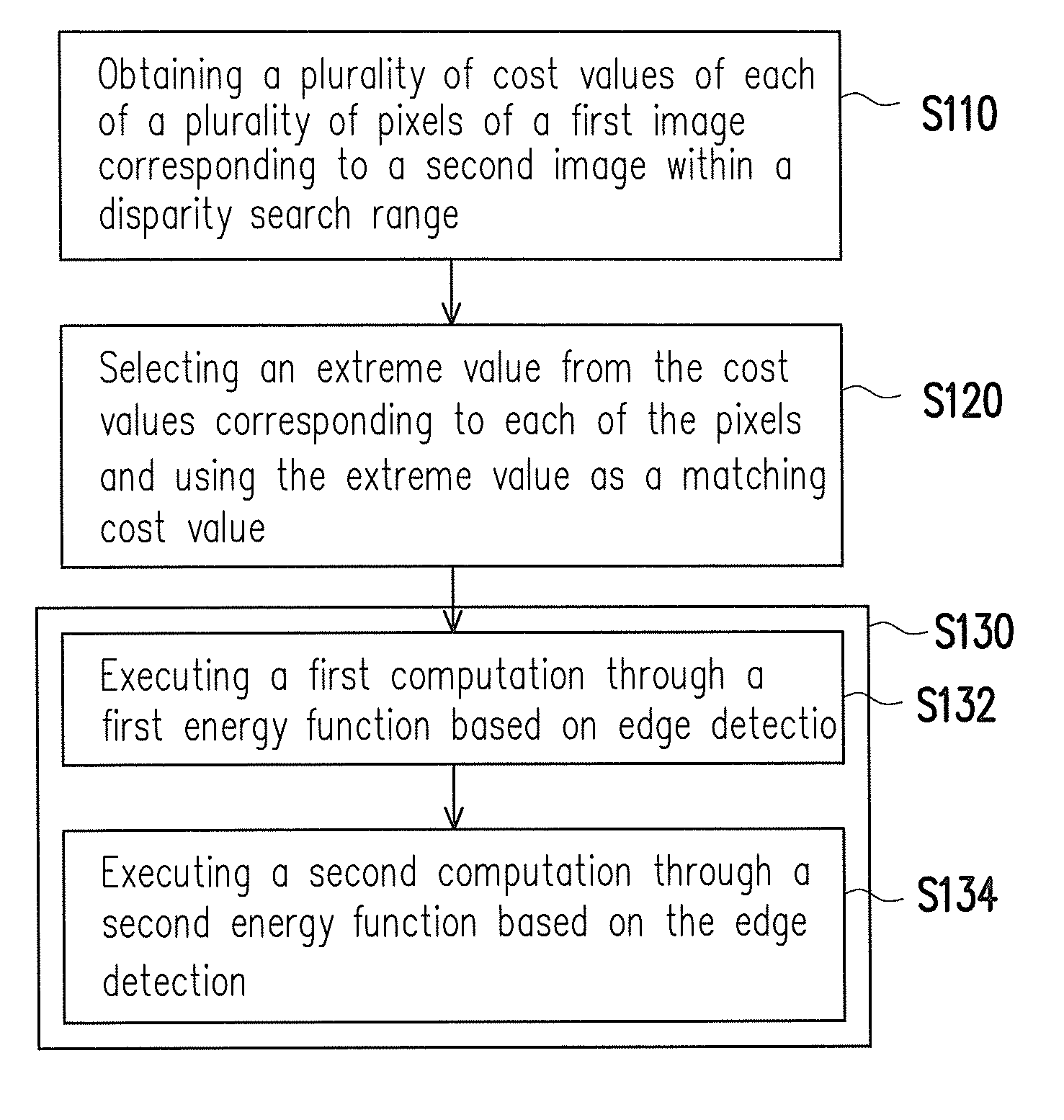
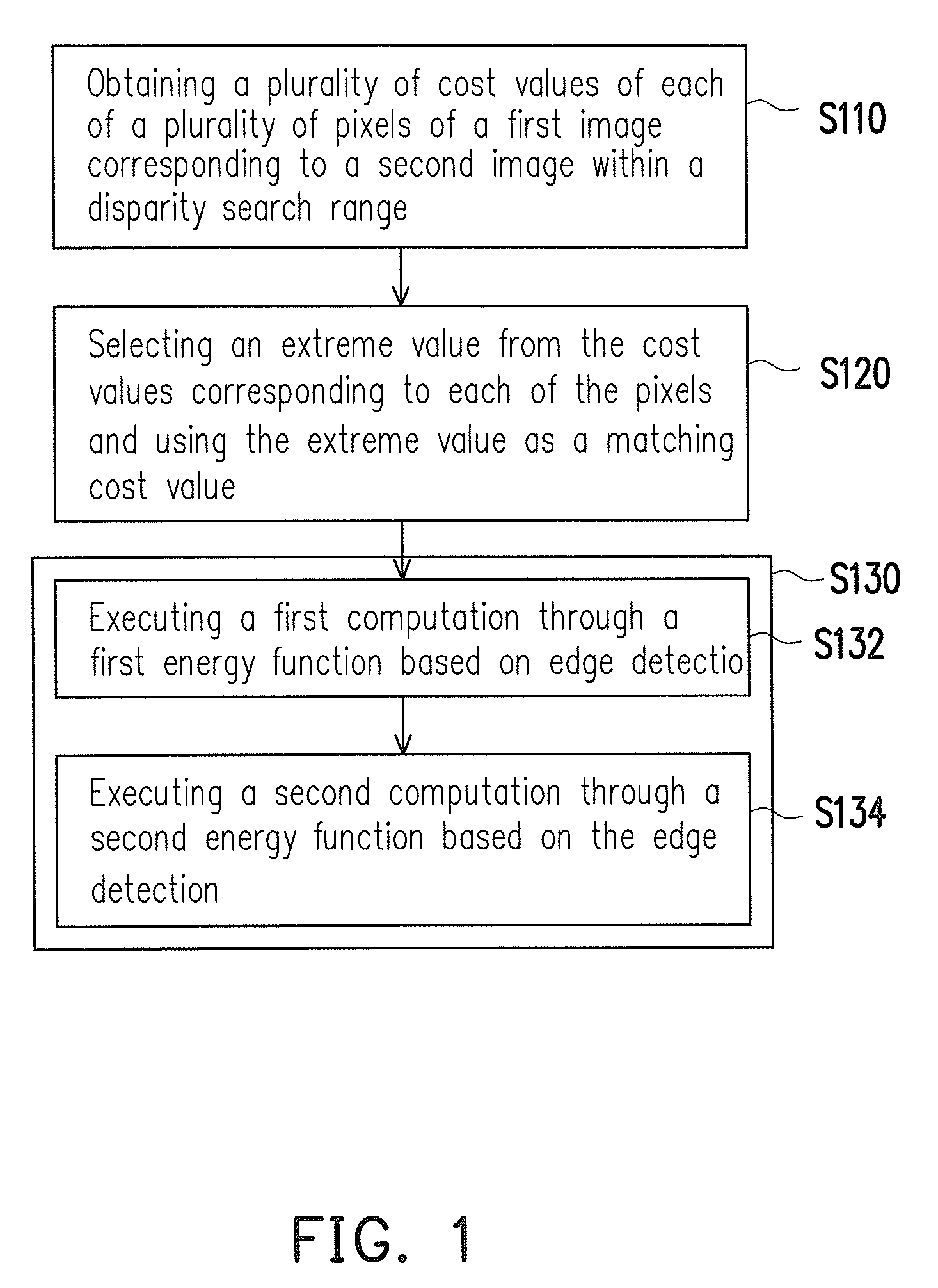
[0020]FIG. 1 is a flowchart illustrating a disparity estimation method of stereoscopic images according to the first embodiment of the present disclosure. The method is adapted to an electronic apparatus having a computation function. For example, the electronic apparatus includes a processing unit and a storage unit. A plurality of code segments is stored in the storage unit, and the processing unit performs the disparity estimation method by reading the code segments. The disparity estimation method will described as below. In another embodiment, the disparity estimation method may be implemented in a hardware format, such as one or more chips.

[0021]With reference to FIG. 1, in step S110, a plurality of cost values of each pixel of a first image corresponding to a second image within a disparity search range is obtained. For example, a matching cost computation is executed on the first image and the second image to obtain the cost values. Here, a size of the first image is identic...

second embodiment

[0058]FIG. 5 is a flowchart illustrating a disparity estimation method of stereoscopic images according to the second embodiment of the present disclosure. The method is adapted to an electronic apparatus having a computation function. For instance, the electronic apparatus includes a processing unit and a storage unit. A plurality of code segments is stored in the storage unit, and the processing unit performs the disparity by reading the code segments. The disparity estimation method will described as below.

[0059]With reference to FIG. 5, in step S510, a matching cost computation is executed on a first image and a second image so as to obtain a plurality of cost values of each pixel of the first image corresponding to the second image within a disparity search range. A size of the first image is identical to that of the second image. Then, in step S520, an extreme value is selected from the cost values corresponding to each pixel and used as a matching cost value so as to obtain m...


PUM


Abstract

A disparity estimation method of stereoscopic image is provided. A matching cost computation is executed for a first image and a second image, and one extreme value is selected from cost values corresponding to estimating disparities for each pixel to obtain a matching point corresponding to each pixel. And a matching disparity corresponding to each matching point is adjusted based on edge detection according to a scan order.

Description

CROSS-REFERENCE TO RELATED APPLICATION[0001]This application claims the priority benefit of Taiwan application serial no. 102108061, filed on Mar. 7, 2013. The entirety of the above-mentioned patent application is hereby incorporated by reference herein and made a part of this specification.BACKGROUND[0002]1. Field of the Invention[0003]The present disclosure is directed to a stereo vision technique and more particularly, to a disparity estimation method of stereoscopic images.[0004]2. Description of Related Art[0005]Stereo vision technology is widely applied in various fields in recent years. Generally speaking, the stereo vision includes two stages. In an earlier stage, a disparity map between two images is calculated by using stereo matching, and through trigonometric computations, a depth map may be obtained. In a later stage, images of different viewing angles are produced by using the depth map.[0006]In the earlier stage, disparity estimation includes four steps, matching cost...

Claims


Application Information

Patent Timeline
Patent Type & Authority Patents(United States)
IPC IPC(8): G06K9/00G06T7/00
CPCG06K9/00201G06T7/0075G06T7/0022G06T2207/10012G06T2207/20228G06T7/97G06T7/593G06V20/64
Inventor CHENG, CHAO-CHIEHCHANG, TIAN-SHEUAN
Owner ACER INC
Learn More