Speaker
a technology of piezoelectric speaker and diaphragm, which is applied in the direction of deaf-aid sets, electric transducers, plane diaphragms, etc., can solve the problems of low reproduction sound pressure and small amplitude of diaphragm, and achieve the effect of improving the reproduction sound pressure and reducing the maximum value of stress
- Summary
- Abstract
- Description
- Claims
- Application Information
AI Technical Summary
Benefits of technology
Problems solved by technology
Method used
Image
Examples
embodiment 1
[0038](Embodiment 1)
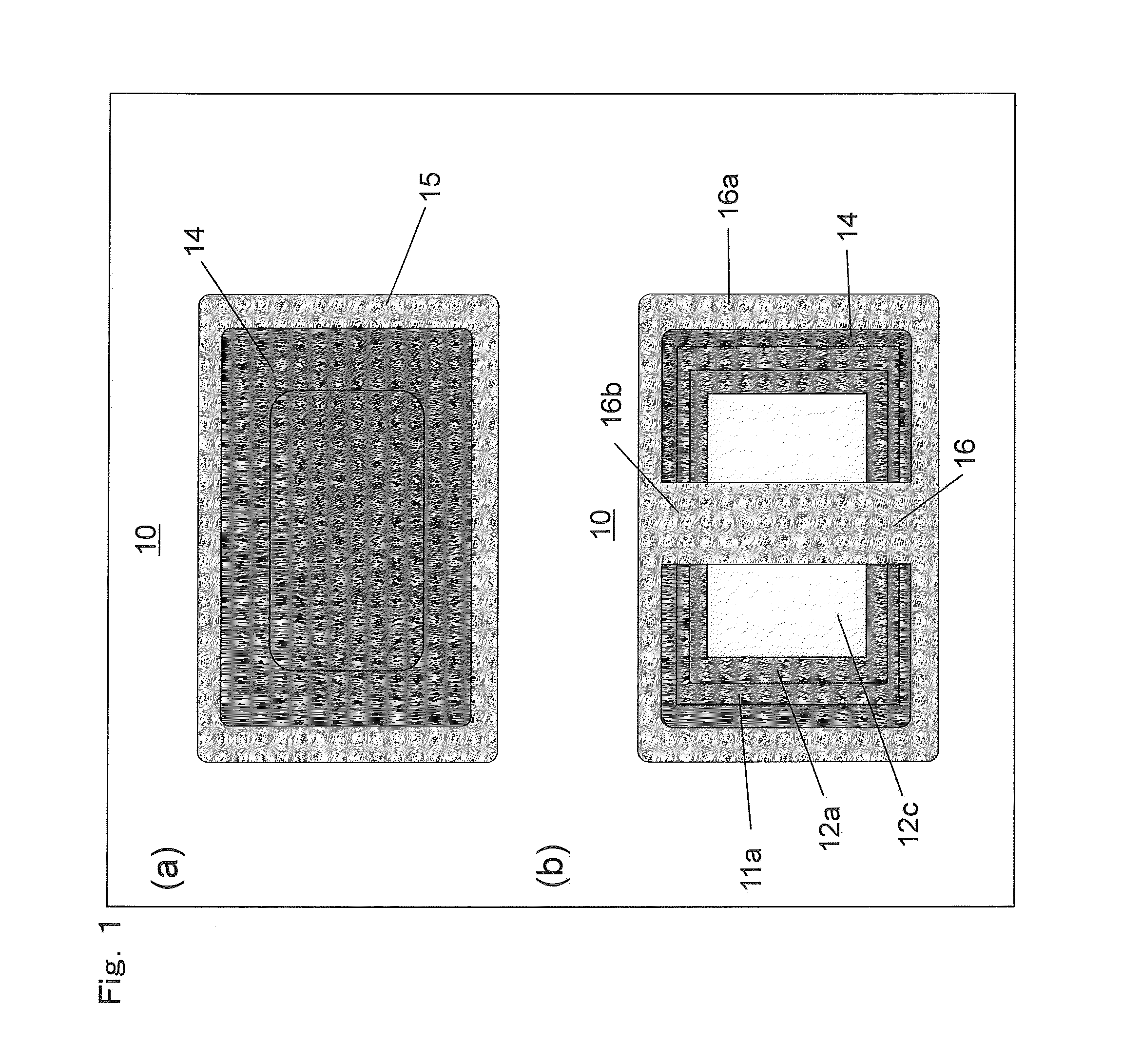
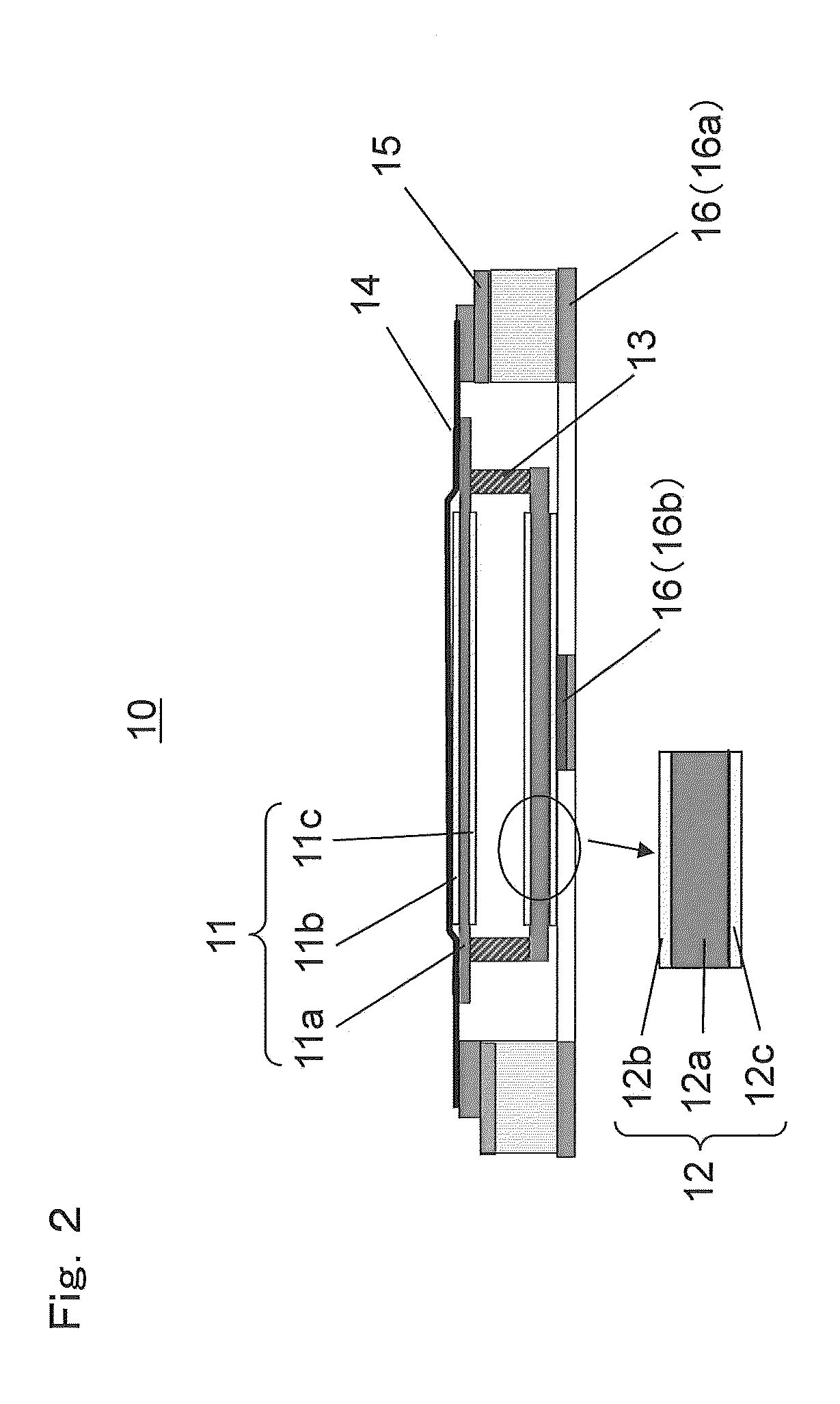
[0039]A piezoelectric speaker according to Embodiment 1 of the present invention includes two piezoelectric diaphragms having stiffnesses different from each other, a connecting member which connects the two piezoelectric diaphragms to each other, and a frame which supports a central portion of the piezoelectric diaphragm that is located at a lower side when the sound radiation surface side of the piezoelectric speaker is defined as an upper side. Of the two piezoelectric diaphragms, the diaphragm having a higher stiffness is used as a piezoelectric diaphragm having a higher maximum value of bending stress applied thereto at a time of amplitude. Thus, by controlling a vibration mode of each piezoelectric diaphragm at a time of large amplitude, it is possible to reduce the maximum value of stress, and it is possible to improve the maximum sound pressure at which reproduction is enabled.
[0040]FIG. 1 is a front view (FIG. 1(a)) and a rear view (FIG. 1(b)) of a piezo...
embodiment 2
[0059](Embodiment 2)
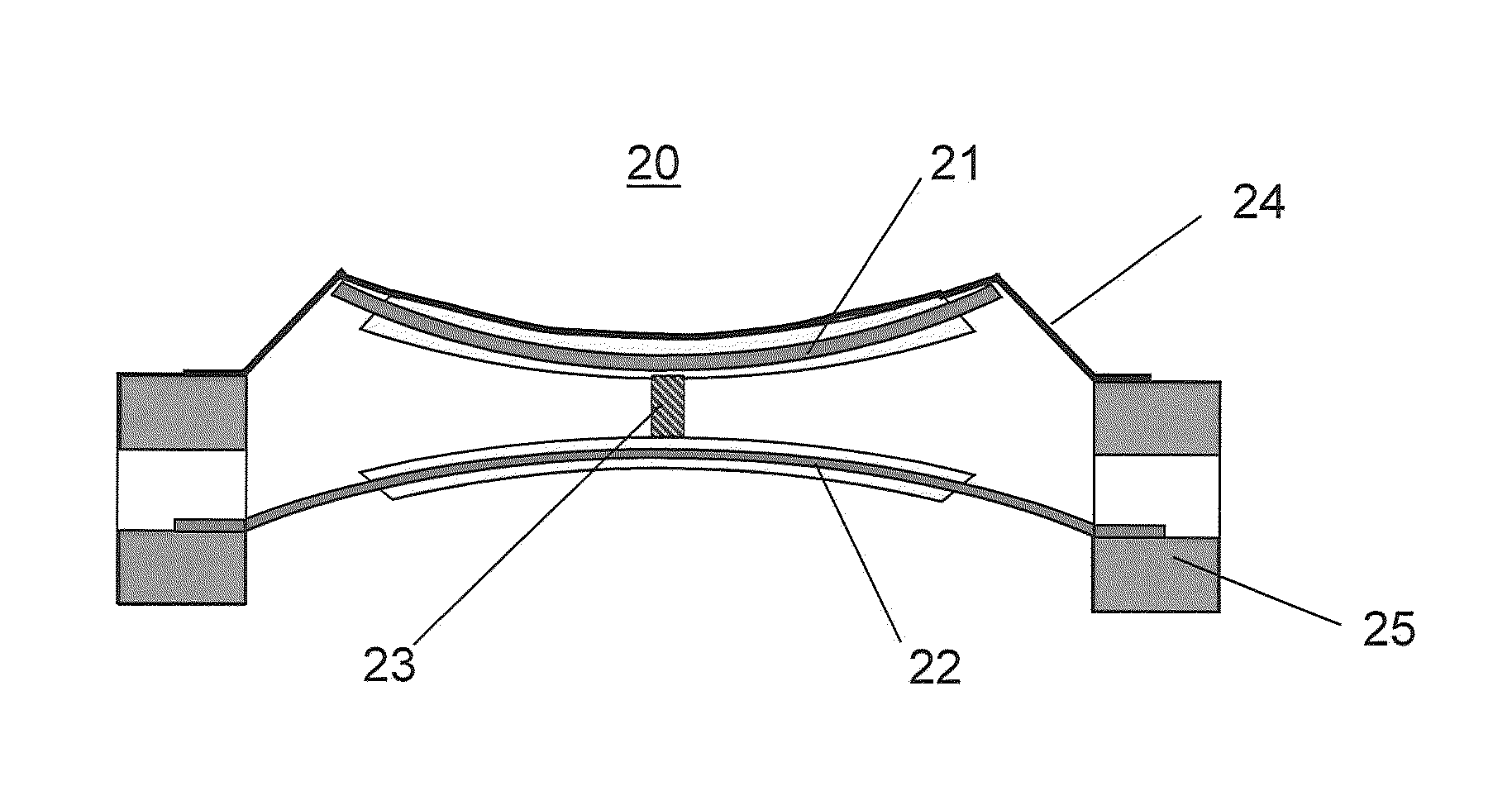
[0060]A piezoelectric speaker 20 according to Embodiment 2 includes two piezoelectric diaphragms having stiffnesses different from each other, a connecting member which connects the two piezoelectric diaphragm to each other, and a frame which supports an end portion of the piezoelectric diaphragm that is located at a lower side (a back side). Of the two piezoelectric diaphragms, the diaphragm having a higher stiffness is used as a piezoelectric diaphragm having a higher maximum value of bending stress applied thereto at a time of amplitude. Thus, by controlling a vibration mode of each piezoelectric diaphragm at a time of large amplitude, it is possible to reduce the maximum value of stress, and it is possible to improve the maximum sound pressure at which reproduction is enabled.
[0061]FIG. 6 is a cross-sectional view of the piezoelectric speaker 20 according to Embodiment 2.
[0062]As shown in FIG. 6, the piezoelectric speaker 20 includes an upper piezoelectric di...
embodiment 3
[0074](Embodiment 3)
[0075]Piezoelectric speakers 30 and 40 according to Embodiment 3 are different from the aforementioned embodiments in that three piezoelectric diaphragms are provided. FIG. 8A is a cross-sectional view of the piezoelectric speaker 30 according to Embodiment 3. FIG. 8B is the piezoelectric speaker 40, of a mode different from FIG. 8A, according to Embodiment 3.
[0076]As shown in FIG. 8A, the piezoelectric speaker 30 includes three piezoelectric diaphragms 31, 32, and 33, a plurality of connecting members 37a, 37b, and 38, an edge 34, an upper frame 35, and a lower frame 36. Each of the piezoelectric diaphragms 31, 32, and 33 is a diaphragm with a bimorph structure. In the respective piezoelectric diaphragms 31, 32, and 33, piezoelectric elements 31b, 31c, 32b, 32c, 33b, and 33c are bonded to both surfaces of respective substrates 31a, 32a, and 33a. It should be noted that in order from the front side of the speaker 30, the piezoelectric diaphragms 31, 32, and 33 ar...
PUM
 Abstract
Description
Claims
Application Information
 - R&D
- Intellectual Property
- Life Sciences
- Materials
- Tech Scout
- Unparalleled Data Quality
- Higher Quality Content
- 60% Fewer Hallucinations
Browse by: Latest US Patents, China's latest patents, Technical Efficacy Thesaurus, Application Domain, Technology Topic, Popular Technical Reports.
© 2025 PatSnap. All rights reserved.Legal|Privacy policy|Modern Slavery Act Transparency Statement|Sitemap|About US| Contact US: help@patsnap.com


