
Apparatus and method for producing a signal to reduce the par in a multicarrier system

a multi-carrier system and signal technology, applied in the field of apparatus and method for producing signals, can solve the problems of reducing the efficiency of the overall system, limiting or clipping effects, and increasing the complexity and power consumption of amplifiers, so as to reduce the maximum value of transmission power, reduce the amplitude of transmission signals, and reduce the loss of signal quality. the effect of loss

Active Publication Date: 2010-05-27
RPX CORP +1
View PDF4 Cites 6 Cited by
  • Summary
  • Abstract
  • Description
  • Claims
  • Application Information

AI Technical Summary

Benefits of technology

[0008]One major idea of the inventors is to limit a signal which is to be reduced and has a plurality of subcarriers, in particular the amplitude of the signal, to calculate coefficients for unused subcarriers of the signal from the limited signal, and to use these coefficients to produce a reduction signal which can be combined with the original signal, that is to say the signal to be reduced, in order to reduce the peak values and therefore the PAR of the signal to be reduced. In particular, this makes it possible to achieve frequency-selective limiting of a signal in baseband, which is considerably more efficient than conventional limiting methods, in particular for multicarrier systems such as OFDM and OFDMA transmission systems. In particular, the proposed method and apparatus make it possible to limit the amplitude of transmission signals in digital complex baseband and to reduce the maximum values of the transmission power to a greater extent than is possible when using the conventional methods as explained initially, in particular without any disturbing losses of signal quality.
[0035]The approach makes it possible to use low-power and therefore low-cost amplifiers, in order to achieve a predetermined mean output power without any disturbing losses of signal quality.

Problems solved by technology

One problem is now that, when the PAR is relatively high, the result of limiting or clipping effects.
This increases the complexity and power consumption of the amplifier, and reduces the efficiency of the overall system.
However, this can lead to different signal delays since it is not known from the start how often the iteration loop will be passed through.

Method used


Image

  • Apparatus and method for producing a signal to reduce the par in a multicarrier system
  • Apparatus and method for producing a signal to reduce the par in a multicarrier system
  • Apparatus and method for producing a signal to reduce the par in a multicarrier system

Examples


Embodiment Construction

[0043]Reference will now be made in detail to the preferred embodiments of the present invention, examples of which are illustrated in the accompanying drawings, wherein like reference numerals refer to like elements throughout.

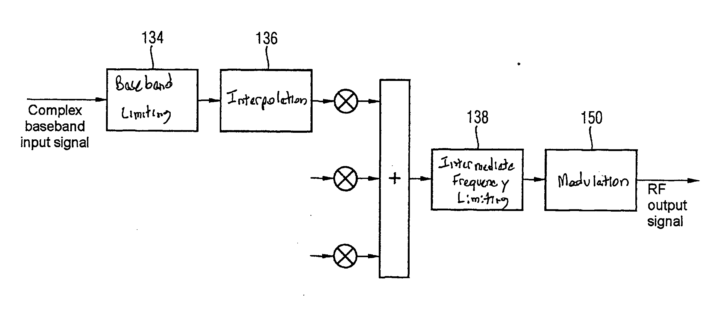
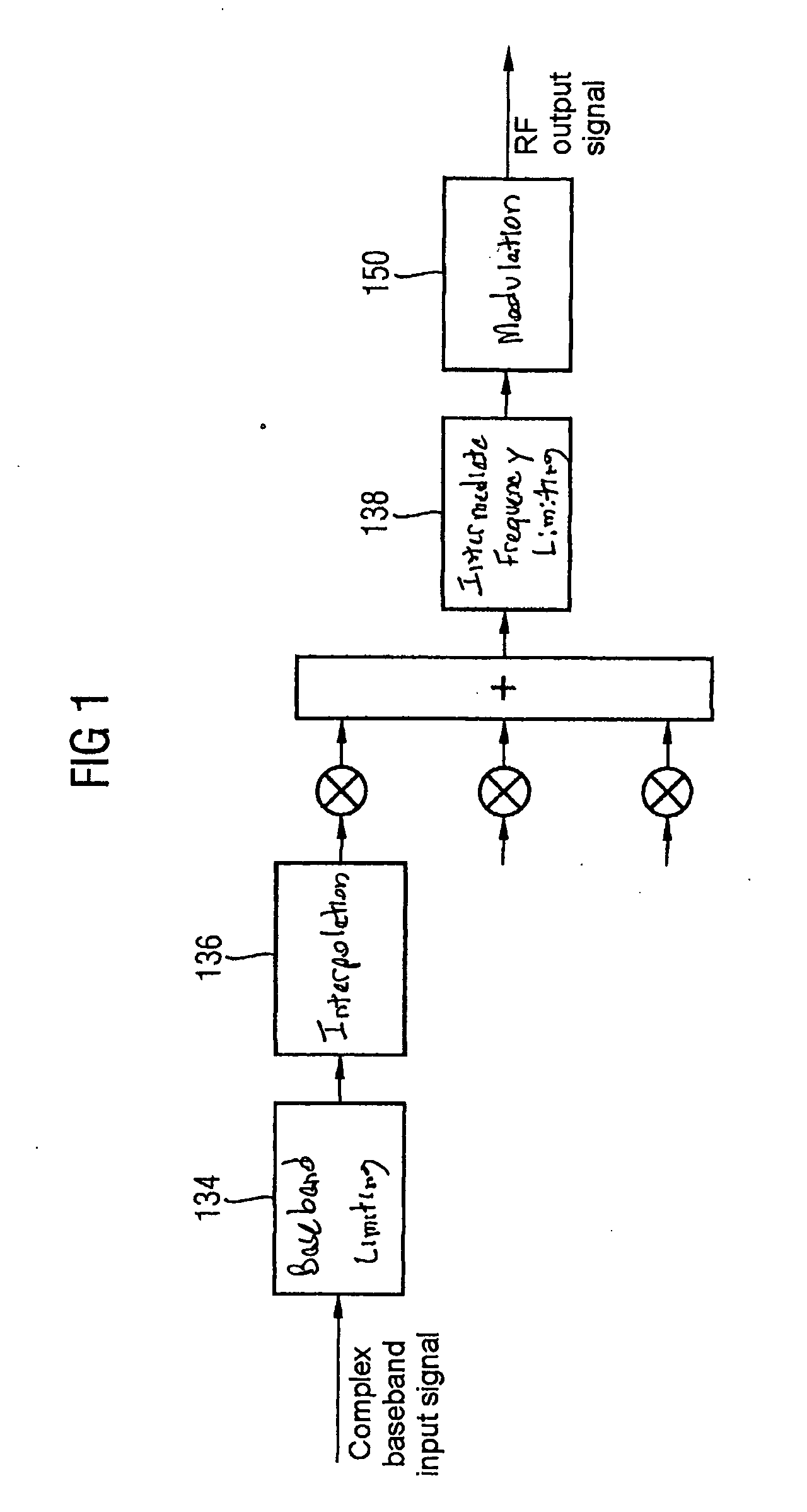
[0044]FIG. 1 illustrates, in a highly simplified form, a transmission system based on the UMTS (Universal Mobile Telecommunications System) example. In particular, the figure also shows a simplified illustration of production of a transmission signal.

[0045]A signal to be transmitted is in this case in the form of an input signal in complex baseband. A baseband limiter (Baseband Clipping) 134 restricts the maximum power of the signal to be transmitted. The bandwidth of the signal is limited by an RRC (Root Raised Cosine) filter in a subsequent block 136 and is raised to a higher sampling rate of a digital intermediate frequency IF by further interpolation filters.

[0046]A mixer provides a frequency offset for the signal. A plurality of complex baseband signals ...


PUM


Abstract

An apparatus produces a reduction signal for a signal having a plurality of subcarriers. The apparatus has a limiter which is designed to produce a limited signal from the signal having a plurality of subcarriers; -a coefficient ascertainment unit which is designed to determine coefficients for unused subcarriers of the signal having a plurality of subcarriers from the limited signal; and -a signal generator which is designed to generate the reduction signal from the coefficients. The reduction signal is able to be combined with the signal in order to form a reduced signal. The coefficient ascertainment unit is designed to project the limited signals onto a K-th base formula.

Description

CROSS REFERENCE TO RELATED APPLICATIONS[0001]This application is based on and hereby claims priority to PCT Application No. PCT / EP2007 / 061437 filed on Oct. 24, 2007 and EP Application No. EP06023834 filed on Nov. 16, 2006, the contents of which are hereby incorporated by reference.BACKGROUND OF THE INVENTION[0002]OFDM (Orthogonal Frequency Division Multiplexing) and OFDMA (Orthogonal Frequency Division Multiple Access)-based mobile radio standards are multicarrier systems. The combination of the individual carriers results in a signal whose maximum instantaneous power considerably exceeds the mean power. Furthermore, higher-quality modulation methods, such as QPSK (Quadrature Phase Shift Keying), 8PSK (Phase Shift Keying) and 16 QAM (Quadrature Amplitude Modulation) can also be used with more than two possible information states per transmission symbol, in order to modulate the various carriers that are used. In the case of these modulation methods, constancy of the instantaneous tr...

Claims


Application Information

Patent Timeline
Patent Type & Authority Applications(United States)
IPC IPC(8): H04L27/26
CPCH04L27/2623H04L27/2618
Inventor HASSLER, BERNDJELONNEK, BJOERNWOLFF, GUNTER
Owner RPX CORP
Learn More