
Multifunctional rotary cutting head for cutting devices, and portable devices comprising such a cutting head

a cutting head and multi-functional technology, applied in the direction of portable power-driven tools, metal working devices, mowers, etc., can solve the problems of increased expenses for acquisition and initiation of cutting materials, loss of time and risk of injury, and loss of parts

Active Publication Date: 2016-06-14
PELLENC SA
View PDF6 Cites 11 Cited by
  • Summary
  • Abstract
  • Description
  • Claims
  • Application Information

AI Technical Summary

Benefits of technology

The patent describes a method of producing a cutting tool that allows for easy positioning and withdrawal of the cutting tool, while also automatically blocking certain cutting elements. The cutting tool also features a mechanism to limit the amplitude of the blade support on the drive shaft. Additionally, the patent describes how two parts of the cutting tool can be easily engaged using complementary retaining fixtures. Overall, this cutting tool design allows for improved efficiency and precision in cutting operations.

Problems solved by technology

This situation has additional disadvantages:The need for training the user in the removal (often left-hand thread) / disassembly and re-assembly of the cutting tool supports, requiring the use of cutting tools one always has to keep within reach.Loss of time and risk of injury; loss of parts during removal and re-assembly.
It is clear that such a situation results in increased expenses for acquisition and initiation of the cutting materials.
This tool is not versatile in so far as, even if it allows simultaneous cutting of grass and small woody plants in order to proceed with the fragmentation of the cut materials, it is not suitable for mounting on an edge-trimmer or grass cutter that has to be used in proximity to bard obstacles.

Method used


Image

  • Multifunctional rotary cutting head for cutting devices, and portable devices comprising such a cutting head
  • Multifunctional rotary cutting head for cutting devices, and portable devices comprising such a cutting head
  • Multifunctional rotary cutting head for cutting devices, and portable devices comprising such a cutting head

Examples


Embodiment Construction

[0103]In the following disclosure and the claims, in order to facilitate the description of the invention, words such as high. “low”, “upper”, “lower”, “lateral”, “upper level”, “lower level” . . . are used in reference to a position of the cutting head in operation, when the axis of said cutting head is oriented vertically. Hence, these words and terms do not have any restrictive character.

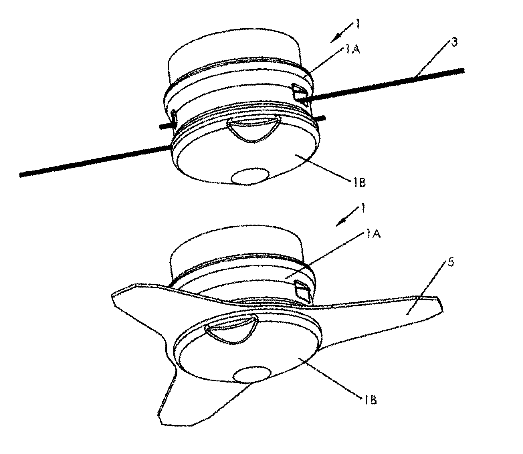
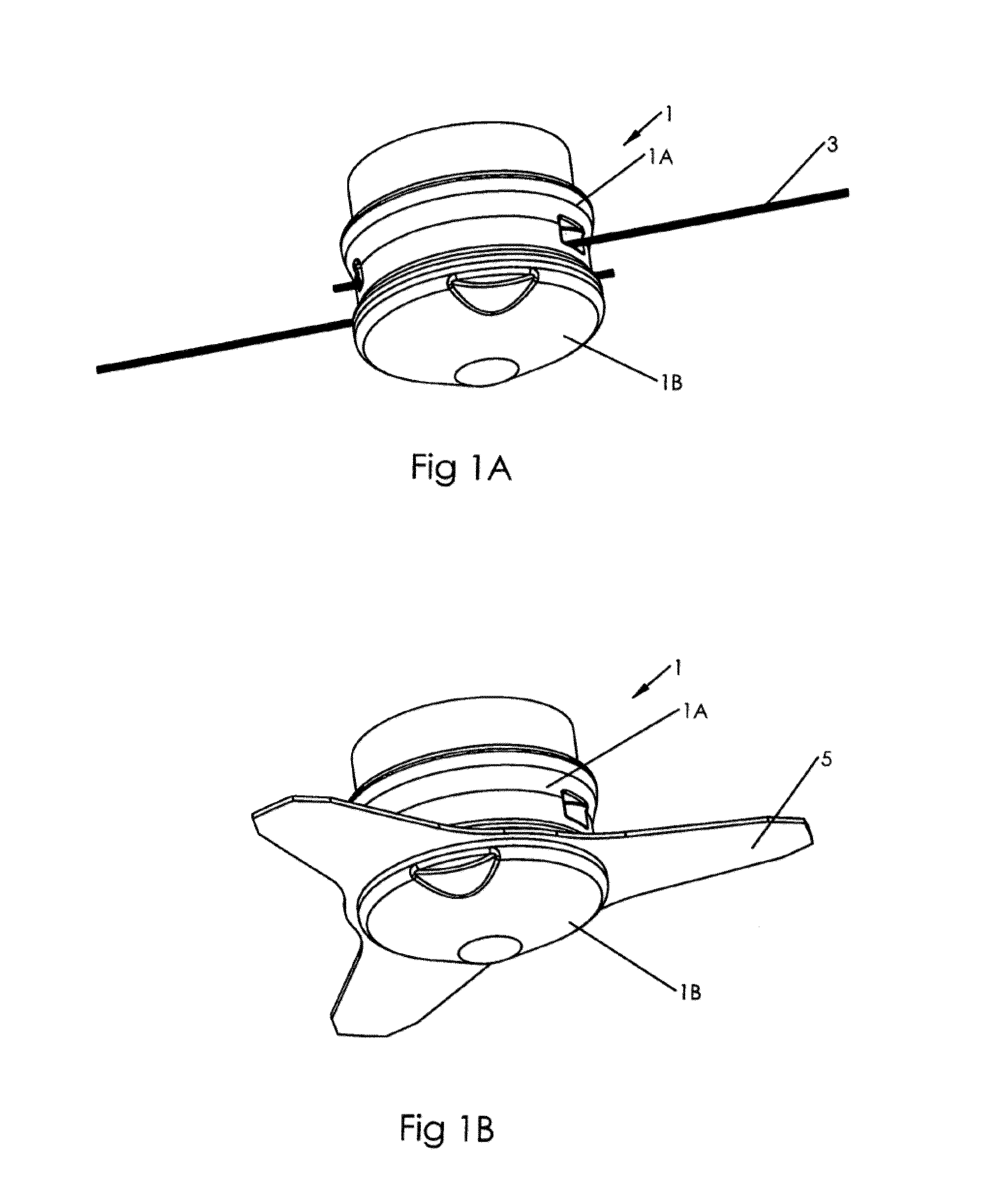
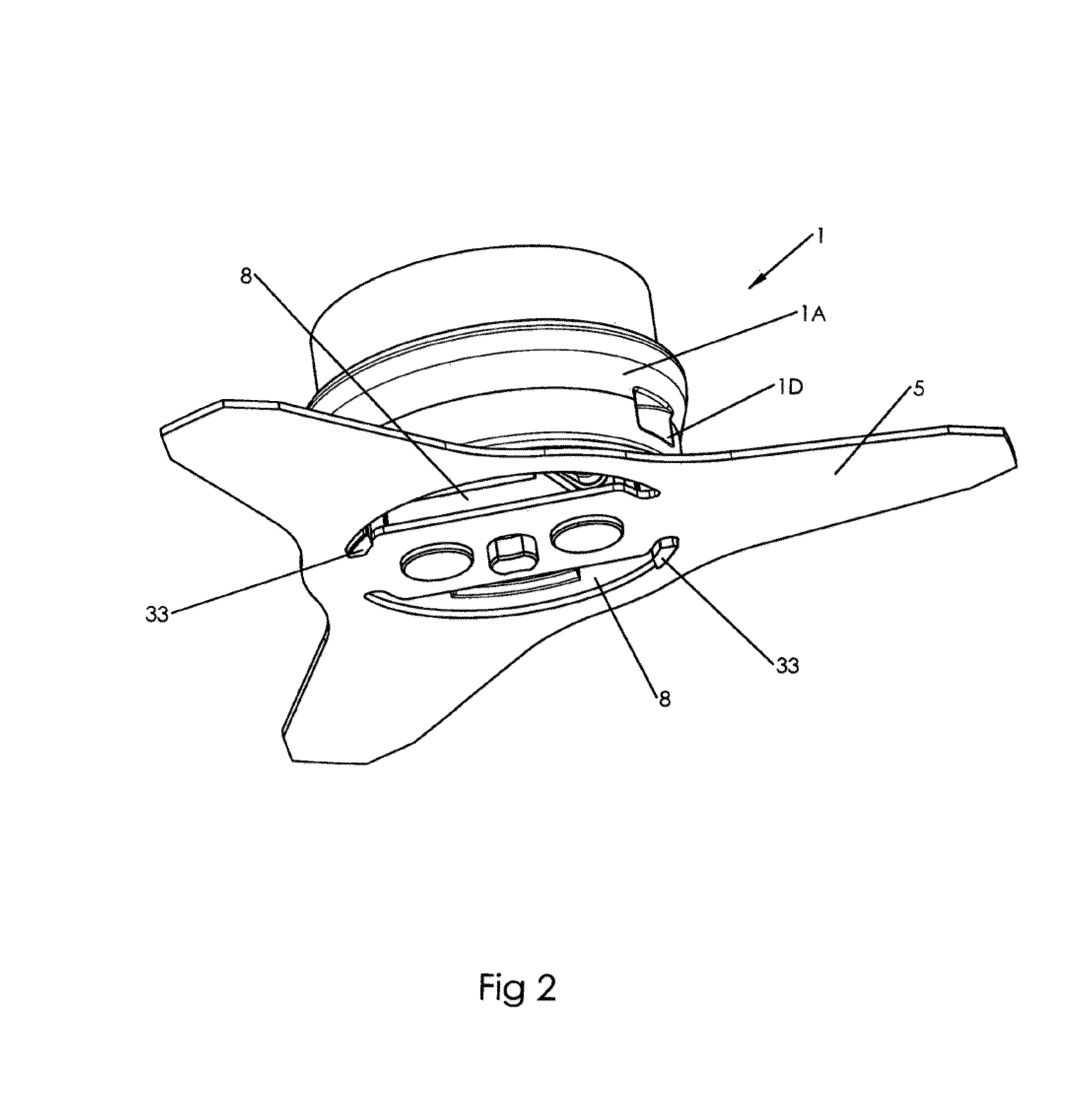
[0104]The cutting head 1 comprises a rotating housing constituted by at least two parts 1A and 1B, or an upper part 1A and a lower part 1B assembled at the base of said upper part, and in which is housed, with an aptitude of axial translation of limited amplitude, a support 2 of cutting element(s) (FIGS. 1A and 1B) or tool(s) 3,5, traversed by an axial drive shaft 6 integral in rotation of said support 2 and whose upper part is fitted so as to permit its coupling to the motor of a portable cutting device, said support of cutting element(s) or tool(s) being mounted with a capability of axial movem...


PUM


Abstract

A multifunctional rotary cutting head is provided for cutting devices as well as portable devices equipped with such a cutting head. The cutting head comprises a rotary housing that has at least a top part and a bottom part and accommodates a support for one or more cutting elements or tools. The support is penetrated by an axial drive shaft on which the support is mounted. The support for the cutting element(s)or tool(s) has two leads to selectively mounting the cutting element(s) or tool(s), i.e. a first level designed to mount strands of cutting wire and a second level designed to mount an interchangeable cutting blade.

Description

CROSS-REFERENCE TO RELATED U.S. APPLICATIONS[0001]Not applicable.STATEMENT REGARDING FEDERALLY SPONSORED RESEARCH OR DEVELOPMENT[0002]Not applicable.NAMES OF PARTIES TO A JOINT RESEARCH AGREEMENT[0003]Not applicable.REFERENCE TO AN SUBMITTED ON COMPACT DISC[0004]Not applicable.BACKGROUND OF THE. INVENTION[0005]1. Field of the Invention[0006]The present invention concerns a multifunctional rotary cutting head. It is more specifically intended for equipping portable cutting tools such as edge-trimmers, also called grass cutters or grass trimmers, brush cutters, motorized grass mowers, grass-trimmers or the like.[0007]2. Description of Related Art Including Information Disclosed Under 37 CFR 1.97 and 37 CFR 1.98[0008]Generally, it is customary to classify under the name of edge-cutter or grass-cutter all devices whose function it is to cut lawns or grasses with low resistance. The cutting heads used for this purpose are generally of the type where the cutting elements are constituted b...

Claims


Application Information

Patent Timeline
Patent Type & Authority Patents(United States)
IPC IPC(8): B26B7/00A01D34/412A01D34/73A01D34/416
CPCA01D34/412A01D34/416A01D34/733A01D34/4166A01D34/902
Inventor PELLENC, ROGER
Owner PELLENC SA
Learn More