
Ramming device to be assigned to a rock breaker

a technology of ramming device and rock breaker, which is applied in the direction of manufacturing tools, portable drilling machines, ways, etc., can solve the problems of affecting the longevity of the assembly, affecting the service life of the compacting member at this junction zone, and affecting the service life of the compacting member. , to achieve the effect of increasing the service life of the compacting member and easy replacemen

Inactive Publication Date: 2008-08-19
MONTABERT SA
View PDF17 Cites 11 Cited by
  • Summary
  • Abstract
  • Description
  • Claims
  • Application Information

AI Technical Summary

Benefits of technology

The invention is a compactor apparatus that is designed to be attached to a jackhammer and improve its mechanical strength. The apparatus includes a compacting member that can be fitted directly onto the jackhammer without needing to remove the tool. The apparatus also includes a frame that acts as a reinforcement by absorbing the forces exerted on the compacting member during compacting. The compacting member is designed to have a better mechanical strength and a longer service life. The apparatus can be easily mounted on a construction machine and is stable and secure. The invention also includes an intermediate wearing part that increases the mechanical resistance of the compacting member. Overall, the invention provides a better and more durable solution for improving the performance of the jackhammer in construction projects.

Problems solved by technology

These forces are transmitted to the arm, which leads to the appearance of considerable stresses in the junction zone between the plate and the arm and may lead to the breakage of the compacting member at this junction zone.
In addition, considerable forces are applied to the jackhammer which adversely affects the longevity of the assembly.
Therefore, the tool must first be removed, which involves awkward manipulations and a waste of time, the construction machine then being immobilized.
In the fairly long term, the compacting member risks being broken.
In addition, the disadvantage associated with the necessary removal of the tool is not resolved by this second known embodiment.

Method used


Image

  • Ramming device to be assigned to a rock breaker
  • Ramming device to be assigned to a rock breaker
  • Ramming device to be assigned to a rock breaker

Examples


Embodiment Construction

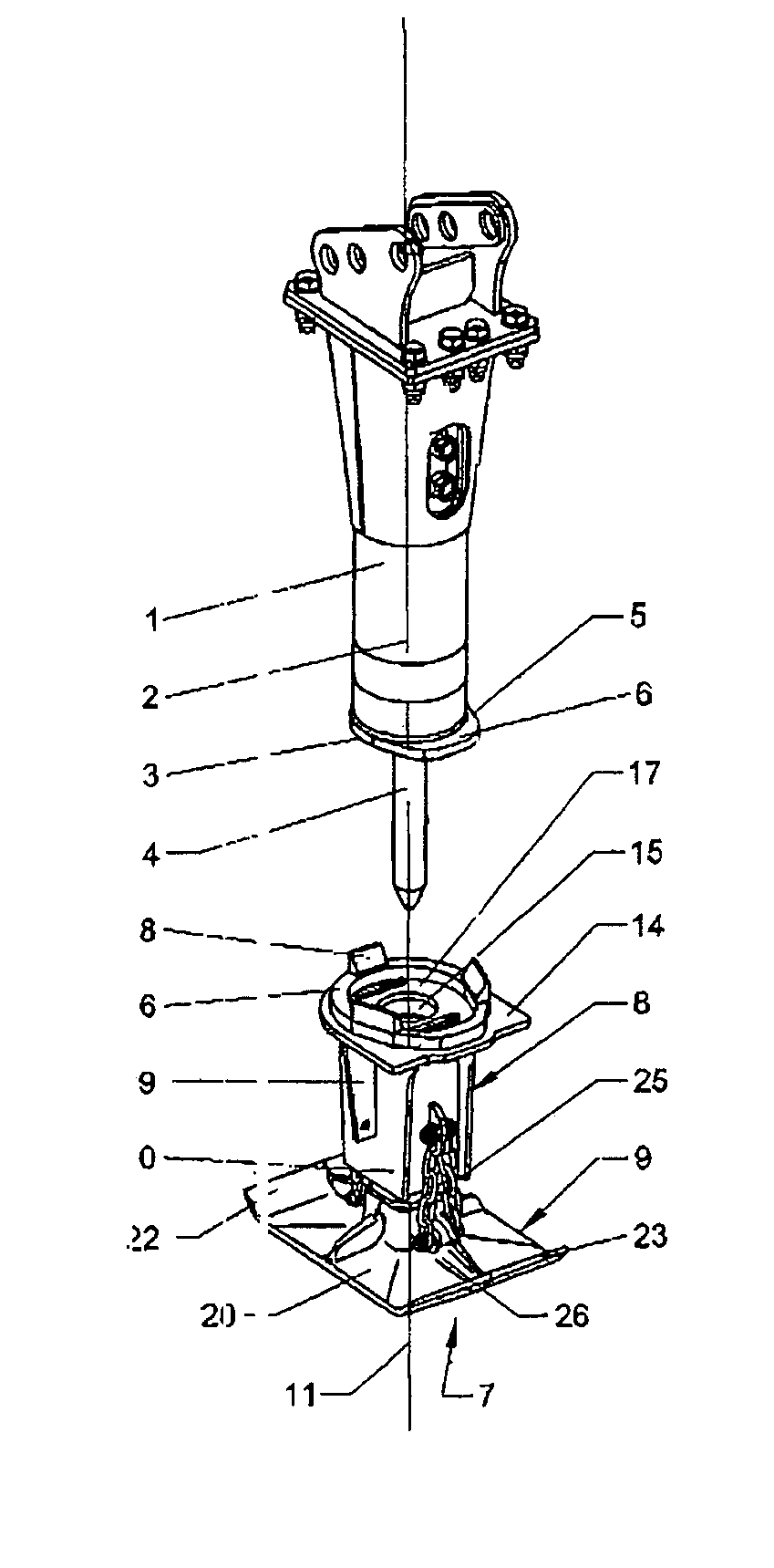
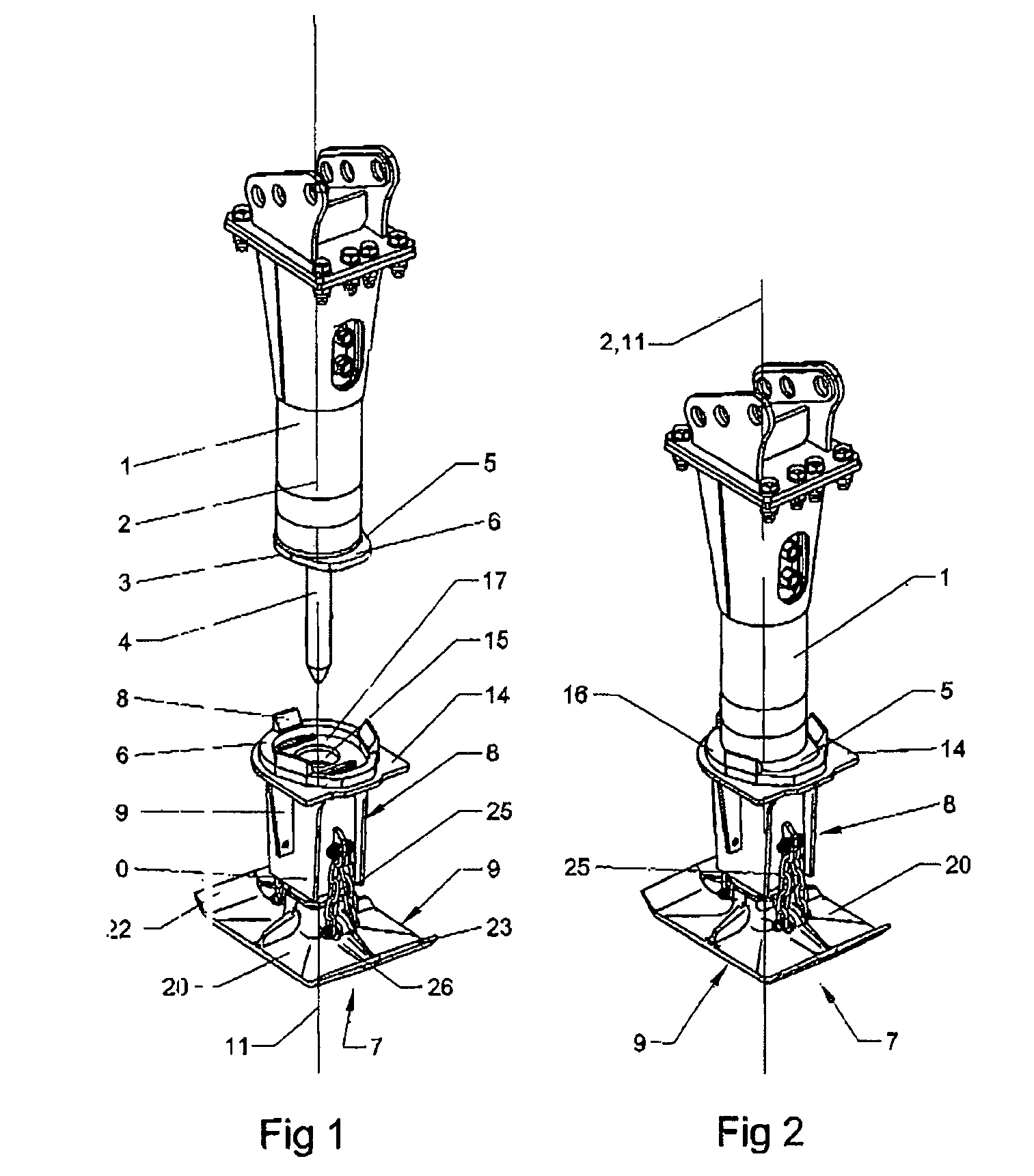
[0037]A hydraulic jackhammer, partially represented in FIGS. 1 and 2, comprises a body 1 of substantially circular cross section with an axis 2, and has an end 3 to which a tool 4 is connected, such as a pickaxe or a chisel. In a known manner, the jackhammer generates impacts, axially, that are transmitted to the tool 4. The end 3 of the body 1 is also provided with a collar 5 having an ovoid cross section and therefore having a portion 6 protruding from the body 1.

[0038]A compactor apparatus 7 is designed to be attached to the end 3 of the jackhammer when it is desired to compact the fragments obtained by action of the jackhammer and its tool 4. The compactor apparatus 7 comprises on the one hand a frame 8 and on the other hand a compacting member 9.

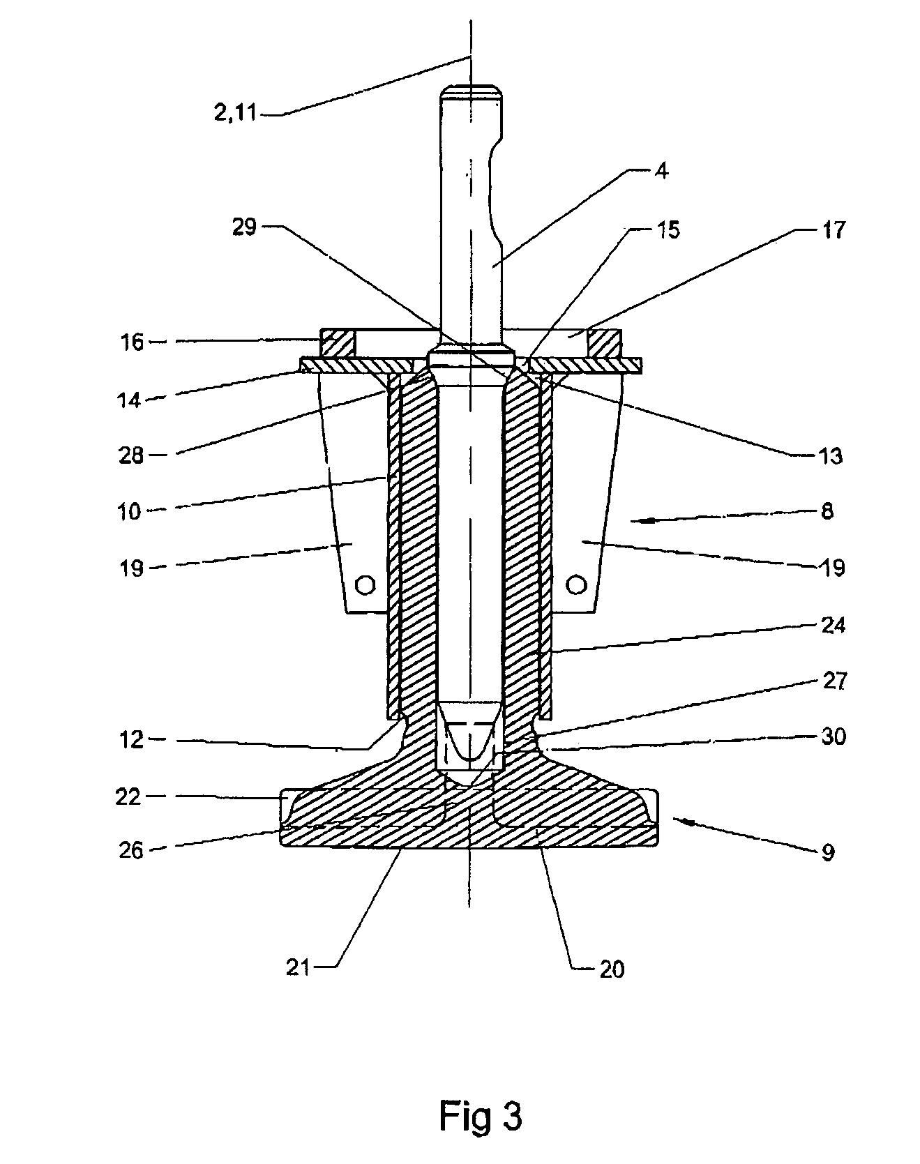
[0039]The frame 8 comprises a hollow tubular body 10, with an axis 11, open at its first axial end 12 and at its second axial end 13, and with a noncircular internal cross section. In the embodiment shown, the body 10 comprises four per...


PUM

PropertyMeasurementUnit
widthaaaaaaaaaa
shapeaaaaaaaaaa
mechanical resistanceaaaaaaaaaa

Abstract

The ramming device comprises a ramming element to be assigned to the end of a rock breaker. The inventive device receives the shocks generated by the rock breaker and transmits them to fragments to be compacted. The ramming device also has a frame comprising: positioning structure for positioning relative to the rock-breaker so that the axis of the frame is coincident with the axis of the rock breaker; joining structure that enable the temporary and removable fixing of the frame to the end of the rock breaker; axially translational guiding structure for guiding the ramming element relative to the frame; structure for blocking the rotation of the ramming element about the axis of the frame, and; structure for limiting the amplitude of this translation.

Description

[0001]The present invention relates to a compactor apparatus designed to be associated with a jackhammer mounted on the arm of a construction machine such as a mechanical shovel.BACKGROUND OF THE INVENTION[0002]Jackhammers, for example hydraulic jackhammers, are used to break up hard ground coverings or layers and to shatter blocks of rock or concrete during groundwork or demolition operations.[0003]The operations of digging and then backfilling trenches usually require, in addition to a jackhammer, other equipment for clearing or compacting the fragments obtained.[0004]Specific compacting machines may be used, such as a plate vibrator or a vibratory rammer, but they are costly and bulky on the worksite. That is why more flexible solutions have been envisaged, consisting in mounting on the jackhammer a compacting member whose upper portion forms an arm designed to allow attachment to the jackhammer and whose lower portion has the shape of a compacting plate.DESCRIPTION OF THE PRIOR ...

Claims


Application Information

Patent Timeline
Patent Type & Authority Patents(United States)
IPC IPC(8): E02D3/00B25D9/04
CPCE02D3/046Y10T279/17923Y10T279/17085E02F5/20B25D17/26
Inventor COMARMOND, JEAN-SYLVAIN
Owner MONTABERT SA
Learn More