Connecting structure of branch connector in fuel pressure accumulating container

a technology of fuel pressure accumulating container and connecting structure, which is applied in the direction of branching pipes, machine/engines, containers, etc., can solve the problems of low tensile strength, low tensile strength, and high cost of forged type or assembled type, so as to reduce fatigue stress, reduce the maximum value of tensile stress, and prevent generation

Inactive Publication Date: 2005-09-15
USUI CO LTD
View PDF13 Cites 7 Cited by
  • Summary
  • Abstract
  • Description
  • Claims
  • Application Information

AI Technical Summary

Benefits of technology

[0019] In other words, the invention is intended to lower the maximum value of tensile stress generated at the inner peripheral edge of the lower end on the branch connector such as the branch pipe and the joint fixture by inserting the distal end of the branch connector deeply through the inner peripheral wall surface of the cylindrical container or the spherical container until it is projected into the flow path so that a fatigue stress generated at the peripheral edge at the lower end of the branch connector such as the branch pipe and the joint fixture is reduced by counterbalancing the internal pressure and the external pressure applied to the projected portion. The joint portion (brazed portion or the portion joined by diffusing bonding) between the branch connector and the cylindrical container or the spherical container is applied with a pressure from the side of the flow path of the branch connector through the wall of the branch connector to strengthen the joint portion.
[0020] The invention is further intended to prevent generation of stress-concentrated point such as conventional point P (in the case of the cylindrical container it may be generated along the axial direction and thus it has directionality, while in case of the spherical container, it may be generated over a whole periphery of the through hole because it has no directionality) by employing a system to provide the flat surface on the inner peripheral wall surface of the cylindrical container or the spherical container so as to be in abutment with the joint through hole, and connect the branch connector into the through hole formed go as to be in abutment with the flat surface.
[0021] The invention is still further intended to reduce a fatigue stress generated at the inner peripheral edge at the lower end of the branch connector such as the branch pipe and the joint fixture by inserting the distal end of the blanch connector deeply through the flat inner peripheral wall surface of the cylindrical container or the spherical container until it is projected into the flow path and counterbalancing the internal pressure and the external pressure applied to the projected portion, and to lower the maximum value of tensile stress generated at the inner peripheral edge of the lower end of the branch connector such as the branch pipe or the joint fixture by the action of stress decentralization associated with the shape effect of the flat inner peripheral wall surface.
[0022] In the invention, the length L of the projection of the distal end of the branch connector from the inner peripheral wall surface of the pressure accumulating container into the flow path may be short. However, actually, the length is preferably nod less than the thickness t of the branch connector in order to generate the external pressure as much as the internal pressure at the projection for balancing them. In other words, the reason is that it is preferable to settle length L of the projection to the value not less than the thickness t of the branch connector in order to reduce the fatigue stress generated at the inner peripheral edge of the lower end of the branch connector by balancing the internal pressure applied to the branch connector and the external pressure applied to the projection. The upper limit value of the length L of the projection is to be determined appropriately by taking the internal diameter, the thickness, and the like of the cylindrical container or the spherical container into account.

Problems solved by technology

However, in such connecting structure, a large stress is generated at the opening end P of the branch connector, such as the branch pipe 112 aid tee branch joint fixture 114 communicating with the pressure accumulating container, due to constantly repeated abrupt variations in supplied pressure of the high-pressure fluid not less than 1000 kgf / cm2, and, especially variations in relative dimensions between the mating members (mating bearing surfaces) due to vibrations applied by an engine and increase and decrease of ambient temperature, and thus it is susceptible to cracking originating from the opening end P, which may results in leakage of fuel or the like from time to time.
However, with the method of employing high-strength steel as a branch connector such as the branch pipe and the joint fixture, there is a problem in durability since the high-strength steel is very hard to weld, and cannot be hardened. by heat processing.
With the method of enhancing the strength of material by heat treatment including carbonitriding and the like, there is a drawback in that the strength cannot be enhanced because brazing filler metal of the brazed article is deteriorated by heat treatment in a furnace, and thus it is intolerable to be used in a high-pressure application.
In addition, the forged type or the assembled type is disadvantageously heavy in weight and expensive.

Method used


Image

  • Connecting structure of branch connector in fuel pressure accumulating container
  • Connecting structure of branch connector in fuel pressure accumulating container
  • Connecting structure of branch connector in fuel pressure accumulating container

Examples


Embodiment Construction

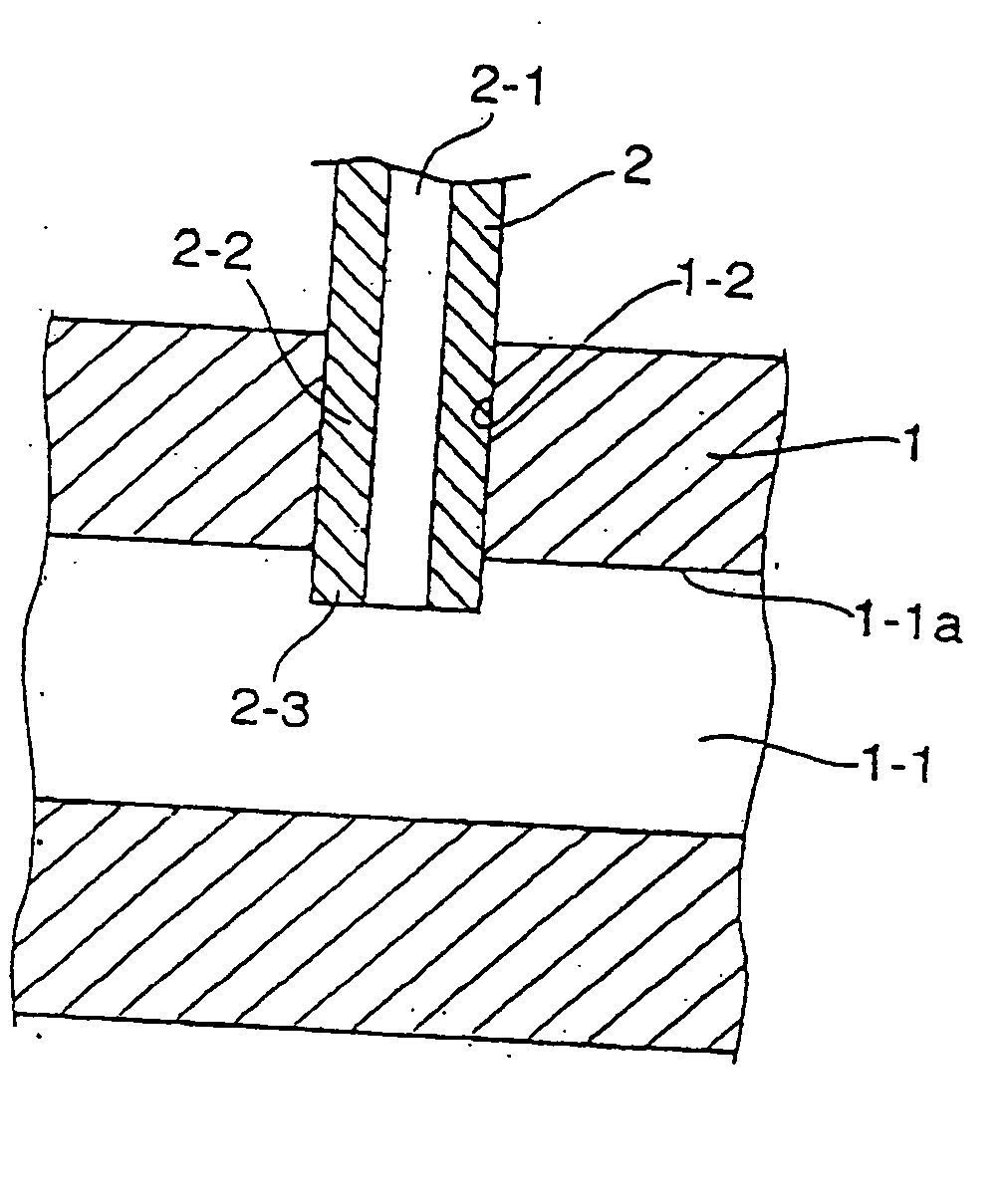
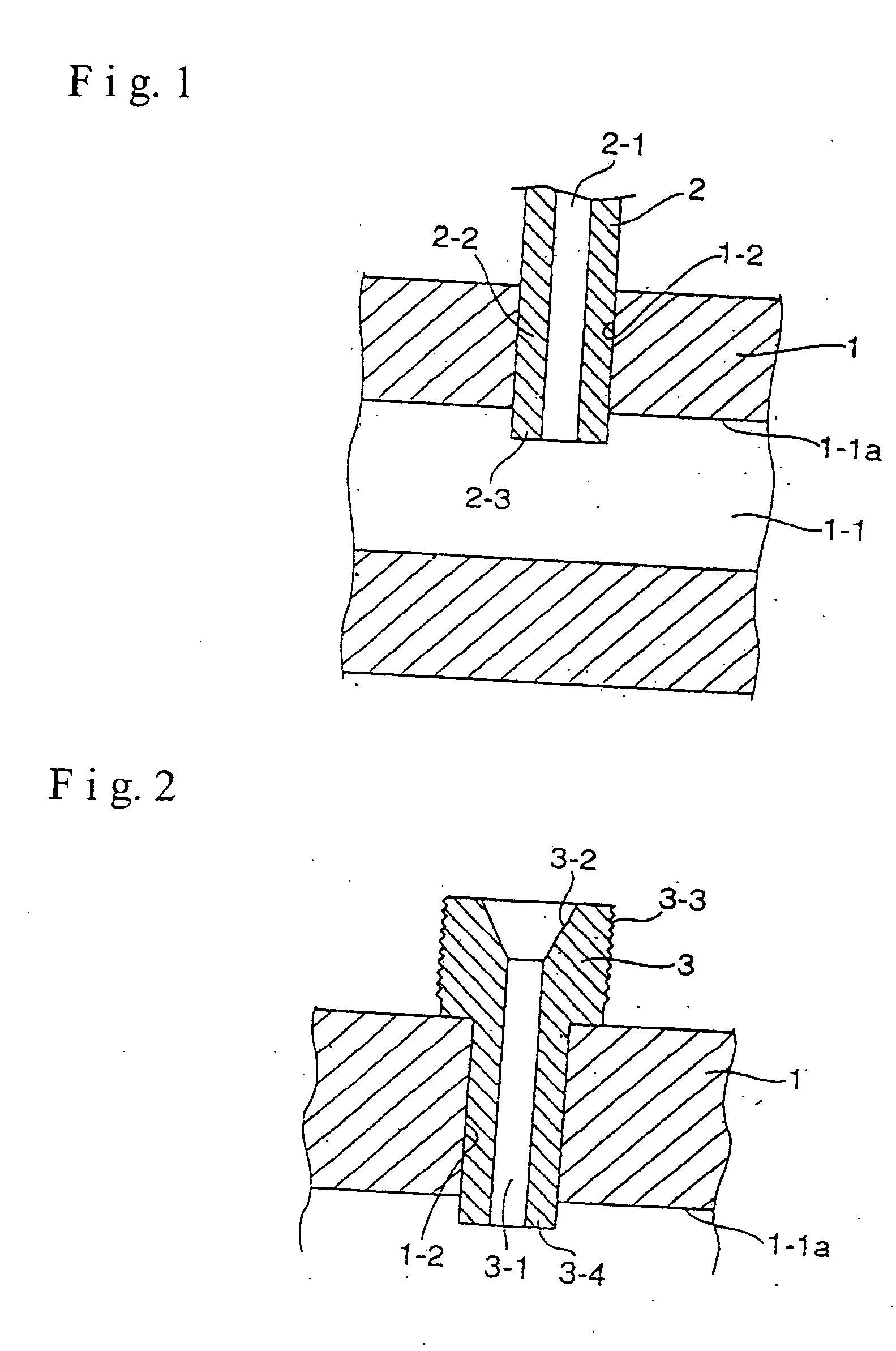
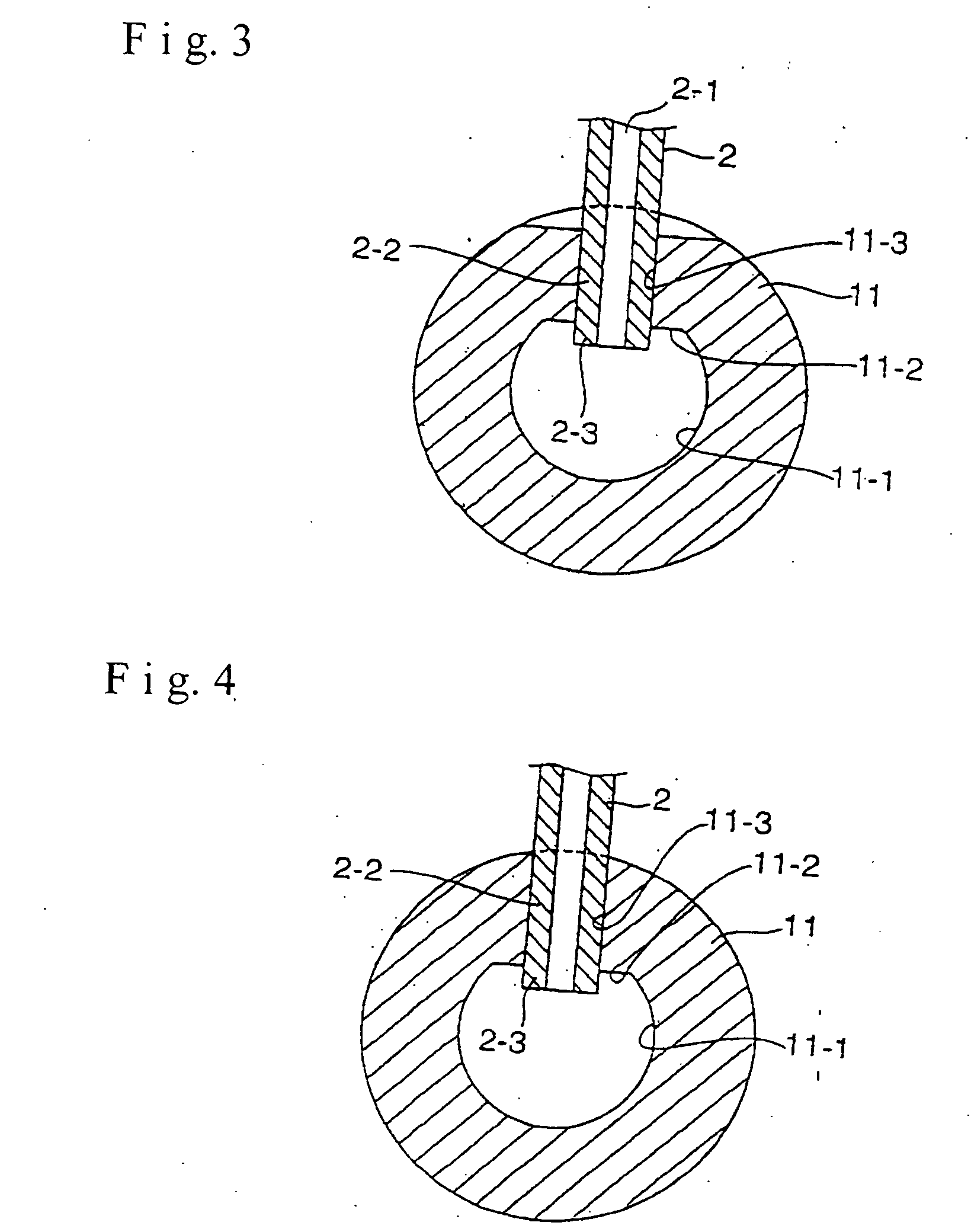
[0053] The cylindrical container 1, 11 having the cylindrical inner peripheral wall surface shown in FIG. 1 to FIG. 6 defines the flow path 1-1, 11-1 therein, and is formed of a thick steel pipe member having a diameter in the order of 30 m / m or less such as a high-pressure piping carbon steel pipe, a stainless steel pipe, or the like. The cylindrical container 1 shown in FIG. 1 and FIG. 2 has a single through hole 1-2 or a plurality of through holes 1-2 at intervals on the inner surface of the peripheral wall in the axial direction so as to communicate with the flow path 1-1. The cylindrical container 11 shown in FIG. 3 to FIG. 6 has a single flat surface 11-2 or a plurality of flat surfaces 11-2 at intervals on the inner surface of the peripheral wall in the circumferential or the axial direction so as to communicate with the flow path 11-1, and a single or plurality of through holes 11-3 are formed into abutment with the flat surfaces so that the centers of the through holes 11-3...


PUM


Abstract

A branch connector in a fuel pressure accumulating container is joined with a through hole formed on a peripheral wall of the pressure accumulating container. The branch connector is inserted deeply into the through hole until the distal end of the branch connector is projected from the inner peripheral wall surface of the pressure accumulating container. Thus, the internal pressure fatigue strength is improved by lowering the maximum stress value generated at the internal peripheral edge at the lower end of the branch connector.

Description

[0001] This application is a divisional of application Ser. No. 10 / 320,855.BACKGROUND OF THE INVENTION [0002] 1. Field of the Invention [0003] The present invention relates to a connecting structure of a branch connector formed of a branch pipe or a joint fixture in a cylindrical fuel pressure accumulating container or a spherical fuel pressure accumulating container such as a high-pressure fuel manifold and a high-pressure fuel block, and, more specifically, to a connecting structure of a branch connector in a fuel pressure accumulating container for supplying a high-pressure fuel not less than 1000 kgf / cm2 in a diesel internal combustion engine. [0004] 2. Description of the Related Art [0005] The cylindrical fuel pressure accumulating container having a cylindrical inner peripheral wall surface includes an cylindrical container 111 having a flow path 111-1 therein, which corresponds to the cylindrical fuel pressure container, and branch pipes 112, which corresponds to the branch c...

Claims


Application Information

Patent Timeline
Patent Type & Authority Applications(United States)
IPC IPC(8): F16L41/08F16L41/00F17C13/00
CPCF02M55/025F17C2260/011F16L41/08F16L41/082F17C13/002F17C2201/0104F17C2201/0128F17C2223/035F17C2201/0138F17C2203/0617F17C2203/0636F17C2203/0639F17C2203/0643F17C2209/2181F17C2209/221F17C2209/224F17C2209/228F17C2209/232F17C2223/036F02M69/465F16L41/00
Inventor USUI, MASAYOSHI
Owner USUI CO LTD
Why Eureka
Try Eureka