Control device and control method for fuel injection valve

a technology of control device and fuel injection valve, which is applied in the direction of electric control, water supply installation, machines/engines, etc., can solve the problems of not being able to sufficiently suppress the delay in the closing of the fuel injection valve after, and the delay in the opening of the fuel injection valve may delay, so as to reduce residual magnetic force, the effect of reducing the maximum value of electromagnetic for

Active Publication Date: 2016-05-12
TOYOTA JIDOSHA KK
View PDF2 Cites 8 Cited by
  • Summary
  • Abstract
  • Description
  • Claims
  • Application Information

AI Technical Summary

Benefits of technology

[0026]In the above configuration, for example, the reference value is set in advance as a value that corresponds to the time from the reference rising detection timing to the reference falling detection timing in the case where the command value of the peak current value coincides with the peak value of the actual exciting current. When the time from the reference rising detection timing to the reference falling detection timing exceeds the reference value, it may be estimated that a peak value of an actual exciting current is larger than a command value of the peak current value, so the peak current value is reduced in this case. Thus, it is possible to reduce the maximum value of the electromagnetic force that can be generated at the fuel injection valve in single fuel injection, and residual magnetic force after the end of energization is allowed to be easily reduced, so it is possible to suppress a delay in the closing of the fuel injection valve after the end of energization.
[0027]On the other hand, when the time from the reference rising detection timing to the reference falling detection timing is shorter than the reference value, it may be estimated that the peak value of the actual exciting current is smaller than the command value of the peak current value, so the peak current value is increased in this case. Thus, it is possible to increase the maximum value of the electromagnetic force that can be generated at the fuel injection valve in single fuel injection, so it is possible to suppress occurrence of an opening failure of the fuel injection valve.
[0028]Thus, with the above configuration, it is possible to appropriately determine the peak current value in consideration of variations in the resistance of the solenoid due to individual difference in terms of manufacturing, aged degradation, and the like.
[0029]A second aspect of the invention provides a control method for a fuel injection valve. The control method includes: controlling open / close operation of the fuel injection valve by passing exciting current through a solenoid of the fuel injection valve that injects fuel supplied from an inside of a delivery pipe, with the use of an electronic control unit; reducing a peak current value of current, with which the solenoid is energized, as a fuel pressure in the delivery pipe at timing of a start of energization of the fuel injection valve decreases, with the use of the electronic control unit; and reducing the peak current value as an amount of fuel discharged from a high-pressure fuel pump to the delivery pipe reduces, with the use of the electronic control unit.

Problems solved by technology

Thus, if the peak current value is excessively reduced, when the fuel pressure in the delivery pipe increases due to pulsation and then the fuel injection valve becomes hard to open, the opening of the fuel injection valve may delay.
However, with such a method, a delay in the opening of the fuel injection valve is allowed to be avoided, but the peak current value is not allowed to be reduced so much, so it is not possible to sufficiently suppress a delay in the closing of the fuel injection valve after the end of energization.

Method used


Image

  • Control device and control method for fuel injection valve
  • Control device and control method for fuel injection valve
  • Control device and control method for fuel injection valve

Examples


Embodiment Construction

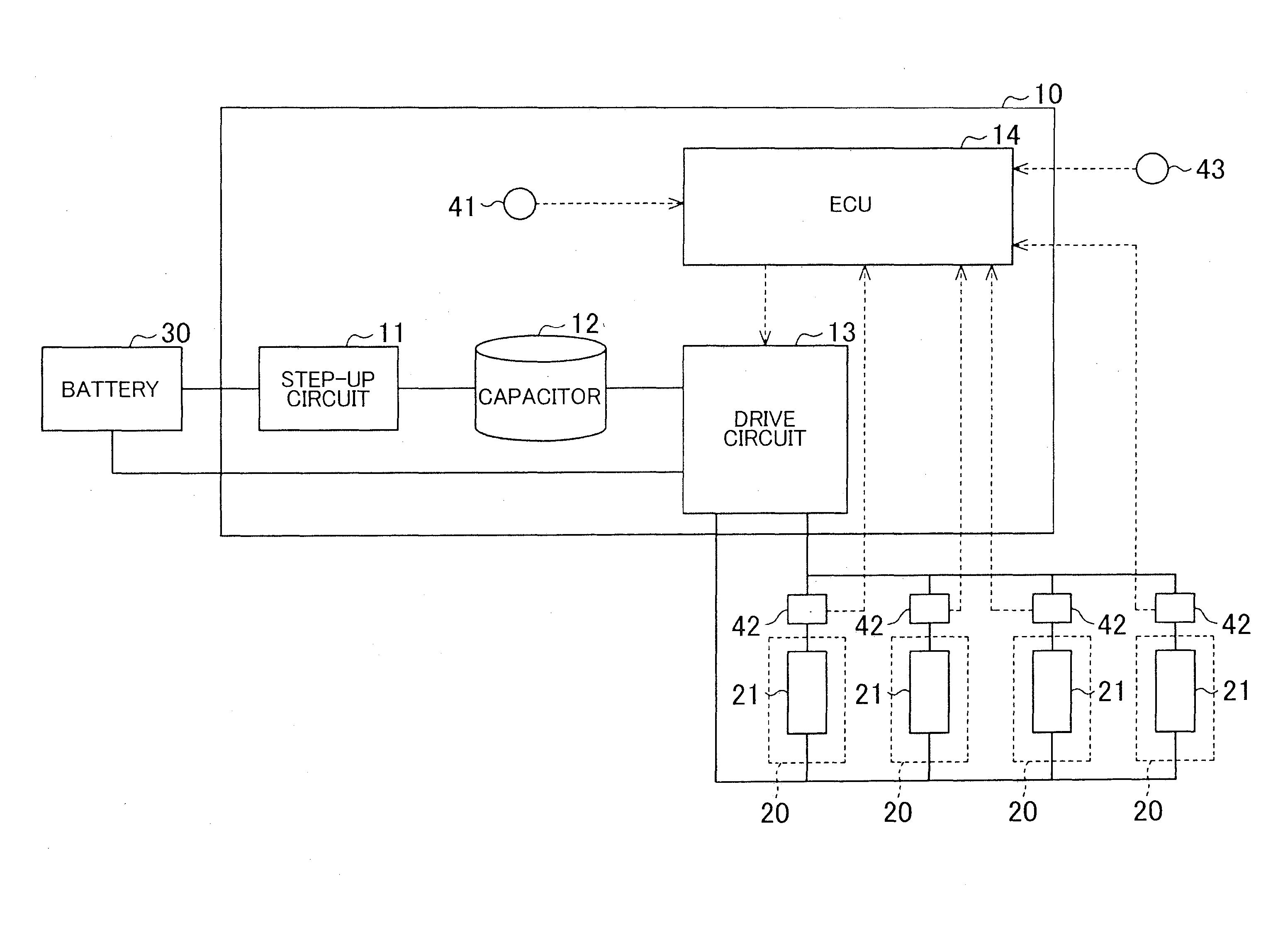
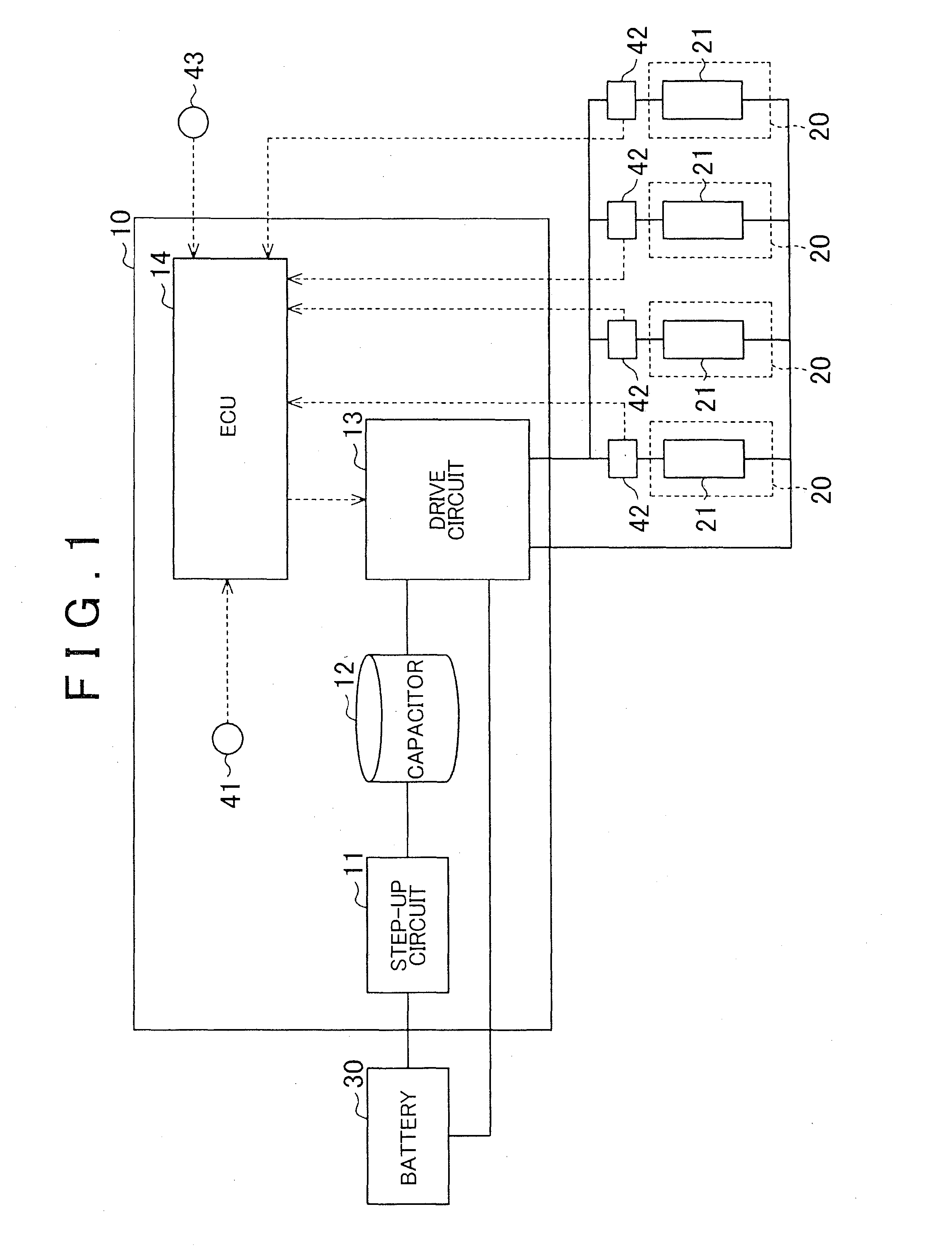
[0047]Hereinafter, one example embodiment of a control device for a fuel injection valve, which causes the fuel injection valve provided in an internal combustion engine to open or close, will be described with reference to FIG. 1 to FIG. 14. FIG. 1 shows a control device 10 for fuel injection valves according to the present embodiment and the plurality of (four in this embodiment) that are controlled by the control device 10. Each of these fuel injection valves 20 is a direct-injection injection valve that directly injects fuel into a corresponding one of combustion chambers of the internal combustion engine.

[0048]As shown in FIG. 1, the control device 10 includes a step-up circuit 11, a capacitor 12 and a drive circuit 13. The step-up circuit 11 steps up the voltage of a battery 30. The battery 30 is provided in a vehicle. The capacitor 12 is charged with the voltage stepped up by the step-up circuit 11. The drive circuit 13 serves as a drive control unit. The drive circuit 13 is ...


PUM


Abstract

A control device for a fuel injection valve includes a drive circuit that controls open/close operation of the fuel injection valve by passing an exciting current through a solenoid of the fuel injection valve and an ECU that reduces a peak current value as a fuel pressure in a delivery pipe at timing of a start of energization of the fuel injection valve decreases. The ECU reduces the peak current value as an amount of fuel discharged from a high-pressure fuel pump to the delivery pipe reduces.

Description

BACKGROUND OF THE INVENTION[0001]1. Field of the Invention[0002]The invention relates to a control device and control method for a fuel injection valve, which cause the fuel injection valve provided in an internal combustion engine to open or close.[0003]2. Description of Related Art[0004]An energization time of a fuel injection valve in single fuel injection is divided into an opening period for opening the fuel injection valve and a holding period for holding the valve-open state of the fuel injection valve. During the opening period, electromagnetic force that is generated at the fuel injection valve gradually increases with an increase in exciting current flowing through a solenoid of the fuel injection valve, and the fuel injection valve is opened. When the exciting current reaches a peak current value that is determined as a current value for reliably opening the fuel injection valve, the opening period ends, and the holding period starts. During the holding period, the exciti...

Claims


Application Information

Patent Timeline
Patent Type & Authority Applications(United States)
IPC IPC(8): F02D41/38F02M51/06F02D41/20
CPCF02D41/38F02D2041/2058F02M51/061F02D41/20F02D41/3836F02D41/3845F02D2041/2017F02D2041/2048F02D2200/0602
Inventor NAKANO, TOMOHIROMURASE, EIJIKANEKO, RIHITO
Owner TOYOTA JIDOSHA KK
Why Eureka
Try Eureka