Crash release mechanism for automotive steering column

a technology of steering column and release mechanism, which is applied in the direction of steering column, steering parts, vehicle components, etc., can solve the problem of difficult control of the crash resistance for

Active Publication Date: 2015-08-18
STEERING SOLUTIONS IP HLDG
View PDF17 Cites 97 Cited by
  • Summary
  • Abstract
  • Description
  • Claims
  • Application Information

AI Technical Summary

Problems solved by technology

However, in such a configuration, a crash resistance force is coupled with the clamping force between the upper and lower jackets.
Thus, the crash resistance force may be difficult to control.

Method used


Image

  • Crash release mechanism for automotive steering column
  • Crash release mechanism for automotive steering column
  • Crash release mechanism for automotive steering column

Examples


Embodiment Construction

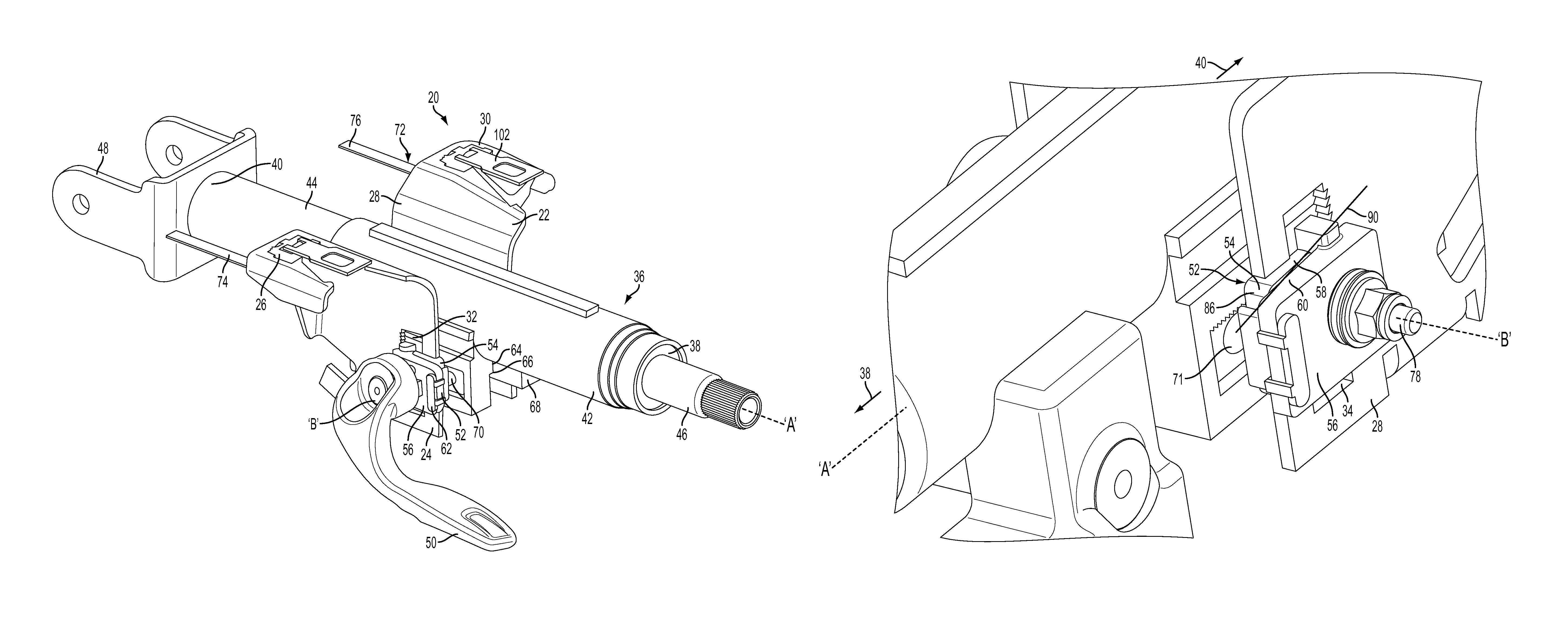
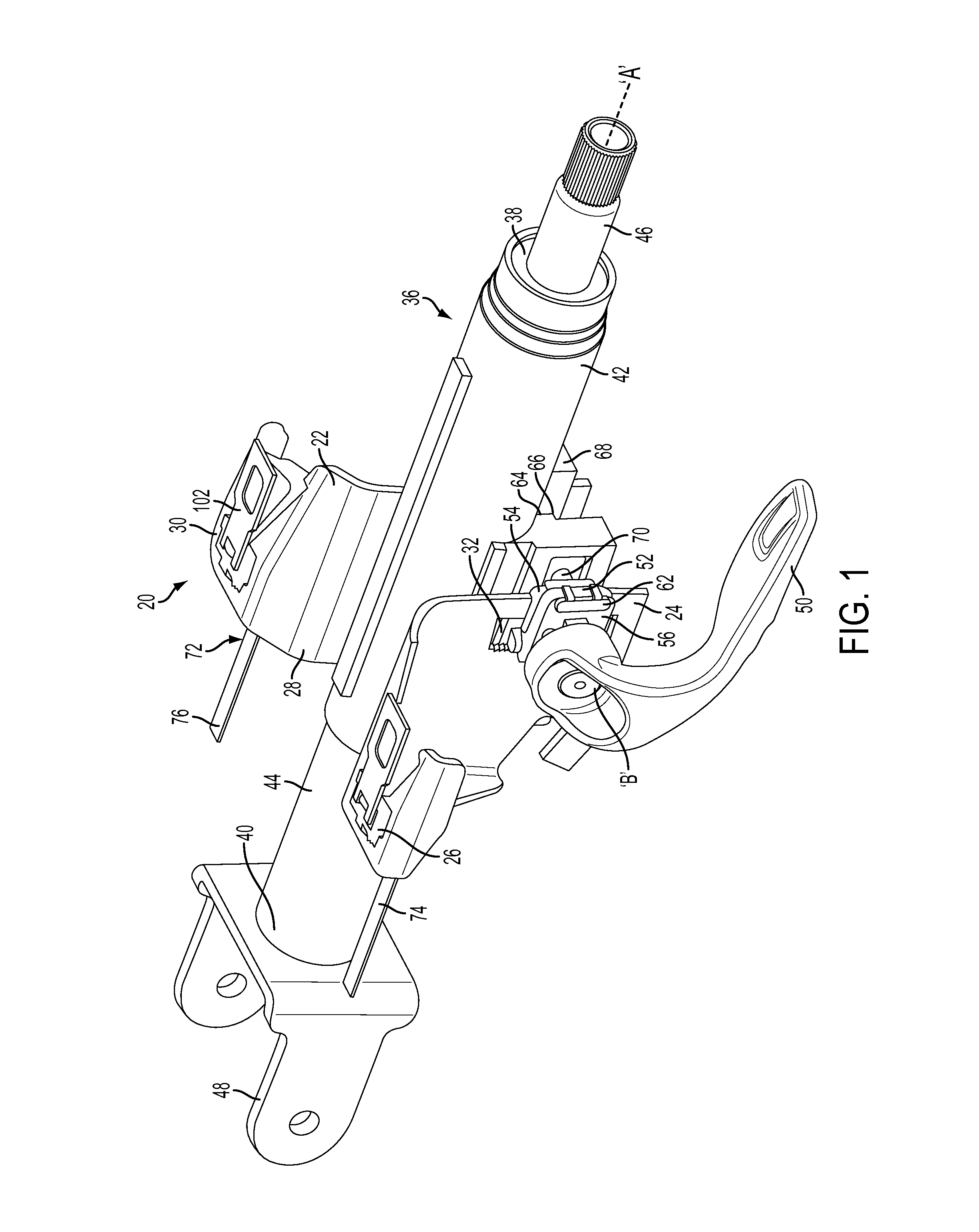
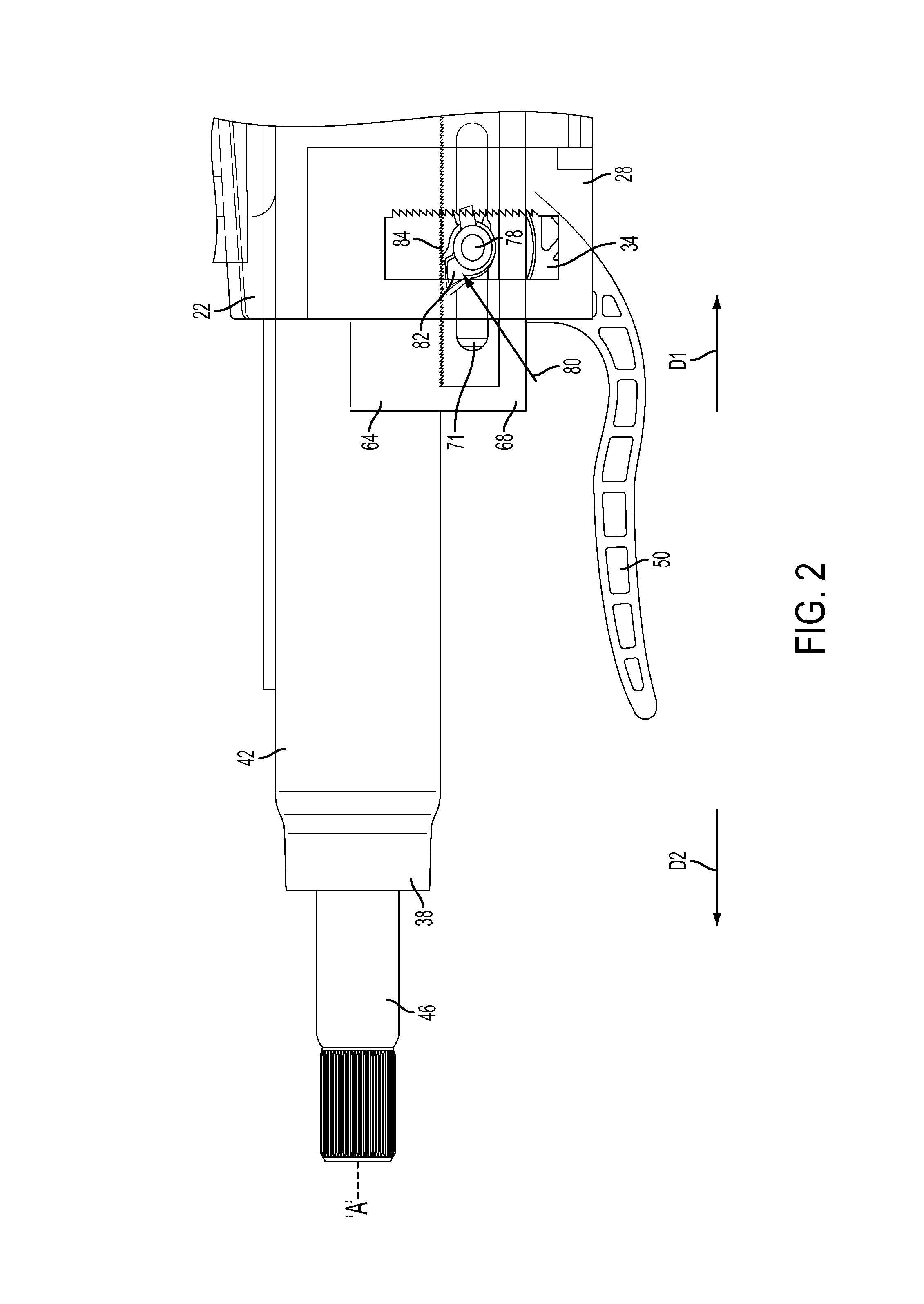
[0017]Referring now to the Figures, where the invention will be described with reference to specific embodiments, without limiting same, FIG. 1 shows a perspective view of an adjustable steering column 20 according to an exemplary embodiment of the present invention. The adjustable steering column 20 includes two operating conditions: an adjustment condition and an energy absorbing condition.

[0018]Referring to FIG. 1, the adjustable steering column includes a mounting bracket 22 configured secure the adjustable steering column in a vehicle. In an exemplary embodiment, the mounting bracket 22 includes a first leg 24 having a first mounting flange 26 extending therefrom, and a second leg 28 having a second mounting flange 30 extending therefrom. The first and second mounting flanges 26, are configured to be secured to an adjacent vehicle component. The first leg 24 includes a first rake slot 32 formed therein, extending in a rake direction. The second leg 28 includes a second rake slo...


PUM


Abstract

An adjustable steering column for a vehicle is provided. The adjustable steering column includes a mounting bracket configured to be secured to an adjacent vehicle component, a compression bracket movably positioned relative to the mounting bracket, and a column jacket extending along a first axis and having an upper jacket and a lower jacket telescopically coupled to one another. The adjustable steering column further includes a locking mechanism movable between a locked position and an unlocked position configured to selectively restrict adjustment of the upper jacket in a telescope direction, and at least one release mechanism configured to allow telescoping movement of the upper jacket with the locking mechanism in the locked position in response to an excessive axial force applied to the column jacket. At least one energy absorbing mechanism is configured to absorb energy during telescoping movement of the upper jacket with the locking mechanism in the locked position.

Description

CROSS-REFERENCES TO RELATED APPLICATIONS[0001]This patent application claims priority to U.S. Provisional Patent Application Ser. No. 61 / 792,833, filed Mar. 15, 2013 which is incorporated herein by reference in its entirety.BACKGROUND OF THE INVENTION[0002]The following description relates to an adjustable steering column, and in particular, a release mechanism in an adjustable steering column.[0003]A steering column may be adjustable in rake and telescope directions. In normal operation, the adjustable steering column is mounted in the vehicle and is selectively adjustable based on a locking condition. In a locked condition, the steering column must sufficiently resist movement or adjustment from a selected position and behave as a stiff extension of an interior vehicle structure. In an unlocked condition, the steering column may be freely adjusted by an operator in the rake and telescope directions.[0004]In high-impact or crash scenarios, it is beneficial for the steering column t...

Claims


Application Information

Patent Timeline
Patent Type & Authority Patents(United States)
IPC IPC(8): B62D1/18B62D1/19B62D1/184
CPCB62D1/195B62D1/184
Inventor STRENG, JOSEPH R.
Owner STEERING SOLUTIONS IP HLDG
Why Eureka
Try Eureka