Devices, systems, and methods for orthodontic hardware

a technology for orthodontic hardware and teeth, applied in the field of orthodontic hardware and/or teeth, can solve the problems of hesitant to employ braces, irritation of lips, cheeks, gums, and/or tongues, and achieve the effect of facilitating engagement and retention of the body and protecting the deficiencies of teeth

Inactive Publication Date: 2015-08-25
THORNTON JUSTIN D
View PDF18 Cites 2 Cited by
  • Summary
  • Abstract
  • Description
  • Claims
  • Application Information

AI Technical Summary

Benefits of technology

[0007]Embodiments of the present invention are directed to various devices, systems and methods of providing an orthodontic appliance in the mouth for shielding deficiencies in one's teeth and / or protecting portions of the mouth from sharp portions of a braces system. For example, in one embodiment, a cap configured to be captured over a bracket of a bracket system for teeth. The cap includes a mound shaped body and multiple tabs. The mound shaped body includes a rounded outer surface extending to a bottom edge and an inner surface defining a hollow space. The bottom edge defines two channels aligned opposite each other. Further, the two channels extend from the bottom edge into the body. The multiple tabs of the cap each extend inward from the bottom edge and are independently moveable. With this arrangement, the tabs facilitate engagement and retention of the body to the bracket.
[0008]In one embodiment, the multiple tabs are resiliently flexible and are moveable from a first, unattached position to a second, attached position, wherein the tabs extend in a substantially common plane in the first, unattached position. Further, in another embodiment, in the second, attached position, the tabs each independently bend relative to structure of the bracket and are each biased toward the first, unattached position such that the tabs retain the body to the bracket. In still another embodiment, the two channels defined in the body include a substantially constant width along their respective length, the width of the two channels being greater than a diameter of an arch wire such that the width of the channels prevent substantially any interference between the body and the arch wire.
[0014]In yet another embodiment, the shield member aesthetically imitates one or more teeth. In another embodiment, the shield member is coupled to another shield member to aesthetically bridge a gap in the teeth.
[0018]In accordance with another embodiment of the present invention, a cap member configured to be positioned over multiple in-line brackets of a bracket system for teeth is provided. The cap member includes an elongated body and multiple tabs. The elongated body extends longitudinally between a first end and a second end thereof. The elongated body includes a rounded outer surface extending laterally between a first side and a second side such that each of the first side and the second side extends to an underside of the elongated body and the rounded outer surface. Also, the elongated body includes an inner surface that defines a hollow space therein. The multiple tabs include a first set of tabs and a second set of tabs. The first set of tabs each extend inward from the first side of the elongated body to define the underside along the first side of the elongated body. Similarly, the second set of tabs each extend inward from the second side of the elongated body to define the underside along the second side of the elongated body. Each of the multiple tabs include a base and a free end such that the first set of tabs extend toward the second set of tabs. With this arrangement, the multiple tabs are independently moveable so as to facilitate engagement and retention to multiple in-line brackets along one's upper or lower teeth.
[0023]In accordance with another embodiment of the present invention, a method for temporarily capping or covering orthodontic hardware inside a mouth of a patient is provided. The method includes providing a cap member including a body with a rounded outer surface extending to a bottom edge and an inner surface defining a hollow space within the body, the cap member including multiple tabs each extending inward from the bottom edge; positioning the multiple tabs of the cap member against a face surface of at least one bracket of the orthodontic hardware; and forcing the cap member against the face surface of the bracket such that the multiple tabs flex and move to a rear side of the at least one bracket so that the at least one bracket is positioned within the hollow space defined by the cap member to retain the cap member to the at least one bracket.

Problems solved by technology

Although braces are an effective tool for ultimately aligning and straightening teeth, some patients are hesitant to employ braces due to financial constraints, the known discomfort and unfavorable appearance of braces, and undergoing the braces process typically taking approximately two and a half years before the braces are removed.
Outside the pressure that braces place on a patient's teeth, discomfort is primarily caused by the brackets and the end of the arch wire, each typically causing irritation to the lips, cheeks, gums, and / or tongue and sometimes causing mucosal ulceration.
However, the efforts proposed to overcome the discomfort of braces or unfavorable appearance require bracket appliances only employable over specialized brackets, an orthodontist to properly position the appliance over the bracket or arch wire, and appliances that interfere with the arch wire.
These issues result in inefficiencies to the patient and are costly.
In addition, due to various factors, such as poor teeth maintenance, limited dentistry and / or orthodontic work, many individuals face issues of tooth loss or the like.
Tooth loss is highly conspicuous and unsightly and, due to financial constraints, often times cannot be fixed or addressed appropriately.

Method used


Image

  • Devices, systems, and methods for orthodontic hardware
  • Devices, systems, and methods for orthodontic hardware
  • Devices, systems, and methods for orthodontic hardware

Examples


Embodiment Construction

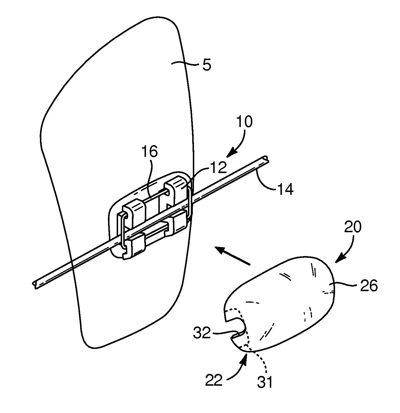
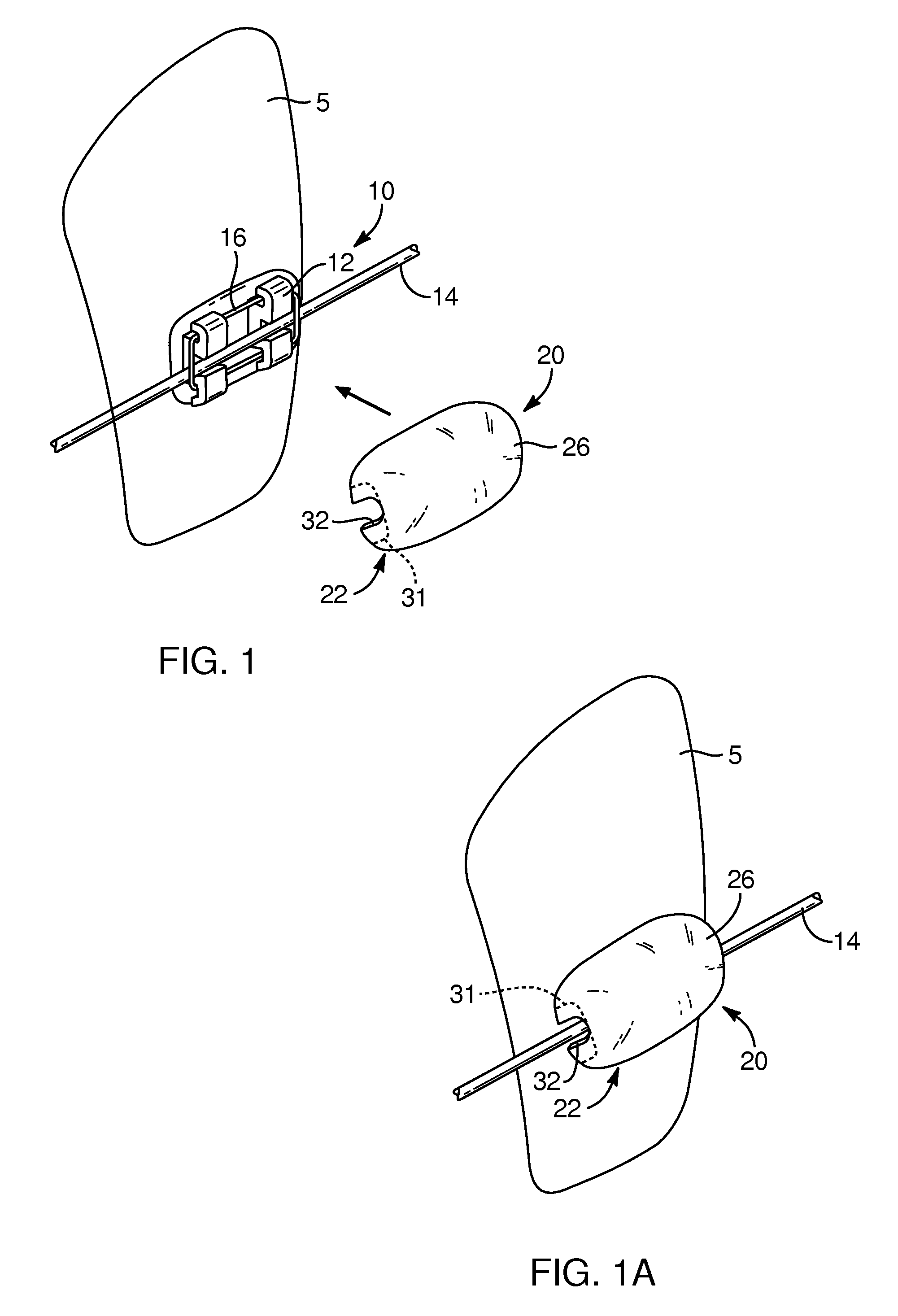
[0049]Referring to FIG. 1, a simplified view of a bracket system 10 or braces system is depicted over a single tooth 5 and a cap 20 in an unattached position. The bracket system 10 may include a bracket 12 coupled and aligned on the teeth with an arch wire 14 or main wire configured to extend through each of the brackets with a ligature wire 16 coupling the arch wire 14 to the bracket 12. The cap 20 may be sized and configured to be captured by the bracket 12 so as to be positioned over the bracket 12, as depicted in FIGS. 1A and 4. Such cap 20 provides a smooth and rounded surface that is non-abrasive to a patient's mouth, such as their lips, cheeks, gums, and tongue. The cap 20 may be formed with one of various shades of white. In another embodiment, the cap 20 may be somewhat transparent.

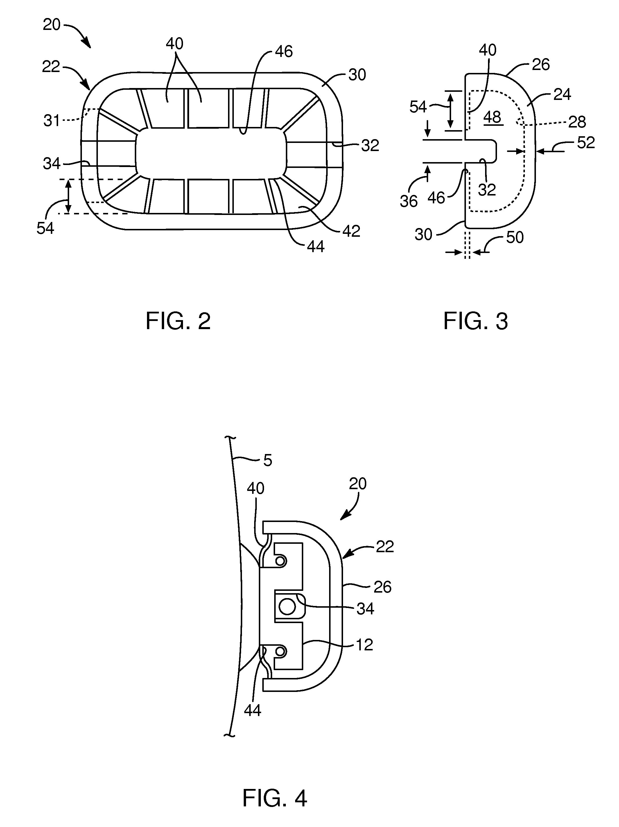
[0050]With respect to FIGS. 1-3, the cap 20, according to one embodiment, may include a rounded body 22 with a mound-like outer shape. The body 22 may include a wall 24 with an outer surface 26 a...


PUM


Abstract

An appliance for orthodontic hardware in the form of a cap sized to fit over a bracket and arch wire braces system. The cap includes a hollowed, mound shaped body with a bottom edge defining an opening on one side of the body. The cap also includes multiple tabs extending from the edge and partially over the opening. The bottom edge also defines two channels aligned opposite each other and extending from the bottom edge. With this arrangement, the cap can be positioned over a bracket with the tabs engaging the bracket and retaining the cap thereto while the channels defined in the body prevent the cap from engaging the arch wire.

Description

CROSS-REFERENCE TO RELATED APPLICATIONS[0001]This application claims the benefit of U.S. Provisional Application No. 61 / 589,485, filed Jan. 23, 2012, and U.S. Provisional Application No. 61 / 703,764, filed Sep. 20, 2012, the contents of each of which are hereby incorporated by reference in their entirety.TECHNICAL FIELD[0002]The present invention relates generally to appliances for orthodontic hardware and / or teeth. More specifically, the present invention relates to devices, systems and methods for shielding orthodontic hardware and / or deficiencies in one's teeth.BACKGROUND[0003]Orthodontic braces are designed to align and straighten teeth and position the teeth in regard to a person's bite as a result of force and pressure on the teeth. The primary components needed to help move the teeth, in the case of traditional metal or wire braces, are brackets, bonding material, an arch wire, and ligature elastic, otherwise known as an “O-ring.” Over a period of time, the teeth move when the...

Claims


Application Information

Patent Timeline
Patent Type & Authority Patents(United States)
IPC IPC(8): A61C7/12A61C5/00A61C13/271
CPCA61C7/125A61C5/002A61C13/26A61C5/20A61C7/14A61C19/063A61M19/00A61M2210/0637
Inventor THORNTON, JUSTIN D.
Owner THORNTON JUSTIN D
Why Eureka
Try Eureka