Annuloplasty devices and related heart valve repair methods

a technology of annuloplasty and heart valve, which is applied in the field of repair and/or replacement of heart valves, can solve the problems of valve leakage, valve support may become non-functional, valve may leakage, etc., and achieves the effect of reducing facilitating better engagement and retention, and reducing the friction between the respective rings

Inactive Publication Date: 2005-11-15
MEDTENTIA INT LTD OY
View PDF33 Cites 289 Cited by
  • Summary
  • Abstract
  • Description
  • Claims
  • Application Information

AI Technical Summary

Benefits of technology

[0010]At least the opposed surfaces of the first and second support rings may be roughened, such as by the use of fabric, coatings, knurling or the like to facilitate better engagement and retention of the support rings on the valve tissue. A removable sleeve may be carried by the first and second support rings for initially reducing friction between the respective rings and the valve tissue during initial engagement therewith, such as during rotation of the device on either side of the annulus. The sleeve may then be removed to expose the higher friction surfaces of the device to the valve tissue for better retention.

Problems solved by technology

The mitral and tricuspid valve leaflets or supporting chordae may degenerate and weaken or the annulus may dilate leading to valve leak (insufficiency).
The leaflets and chords may become calcified and thickened rendering them stenotic (obstructing forward flow).
If the ventricle changes in shape, the valve support may become non-functional and the valve may leak.
In general, annuloplasty rings and replacement valves must be sutured to the valve annulus and this is time consuming and tedious.

Method used


Image

  • Annuloplasty devices and related heart valve repair methods
  • Annuloplasty devices and related heart valve repair methods
  • Annuloplasty devices and related heart valve repair methods

Examples


Embodiment Construction

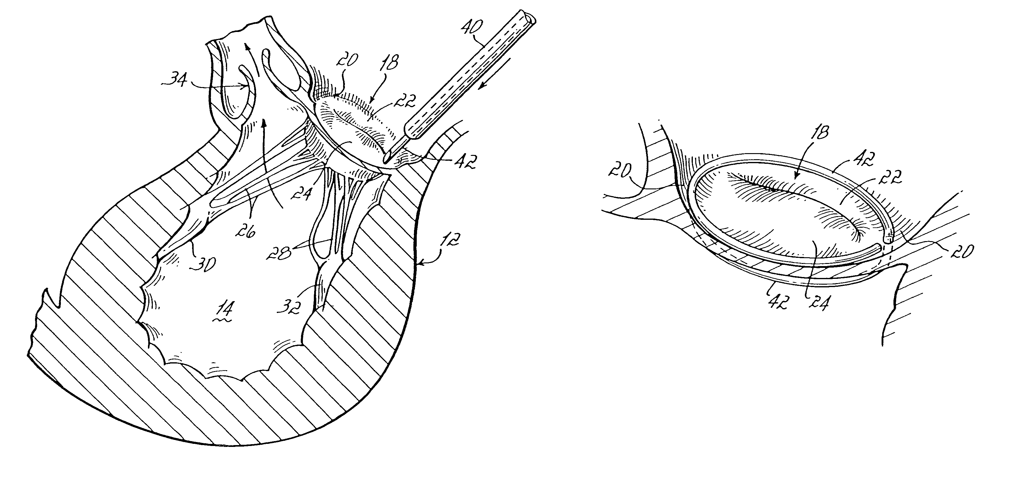
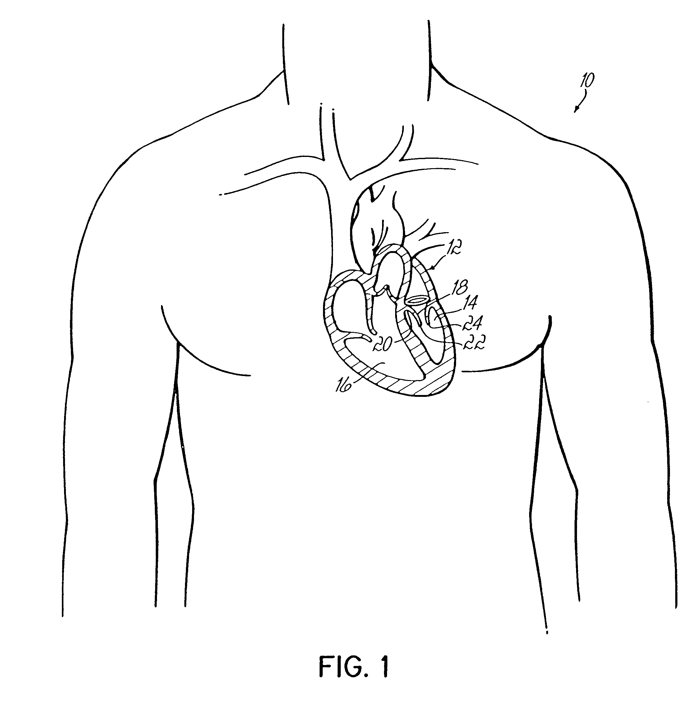
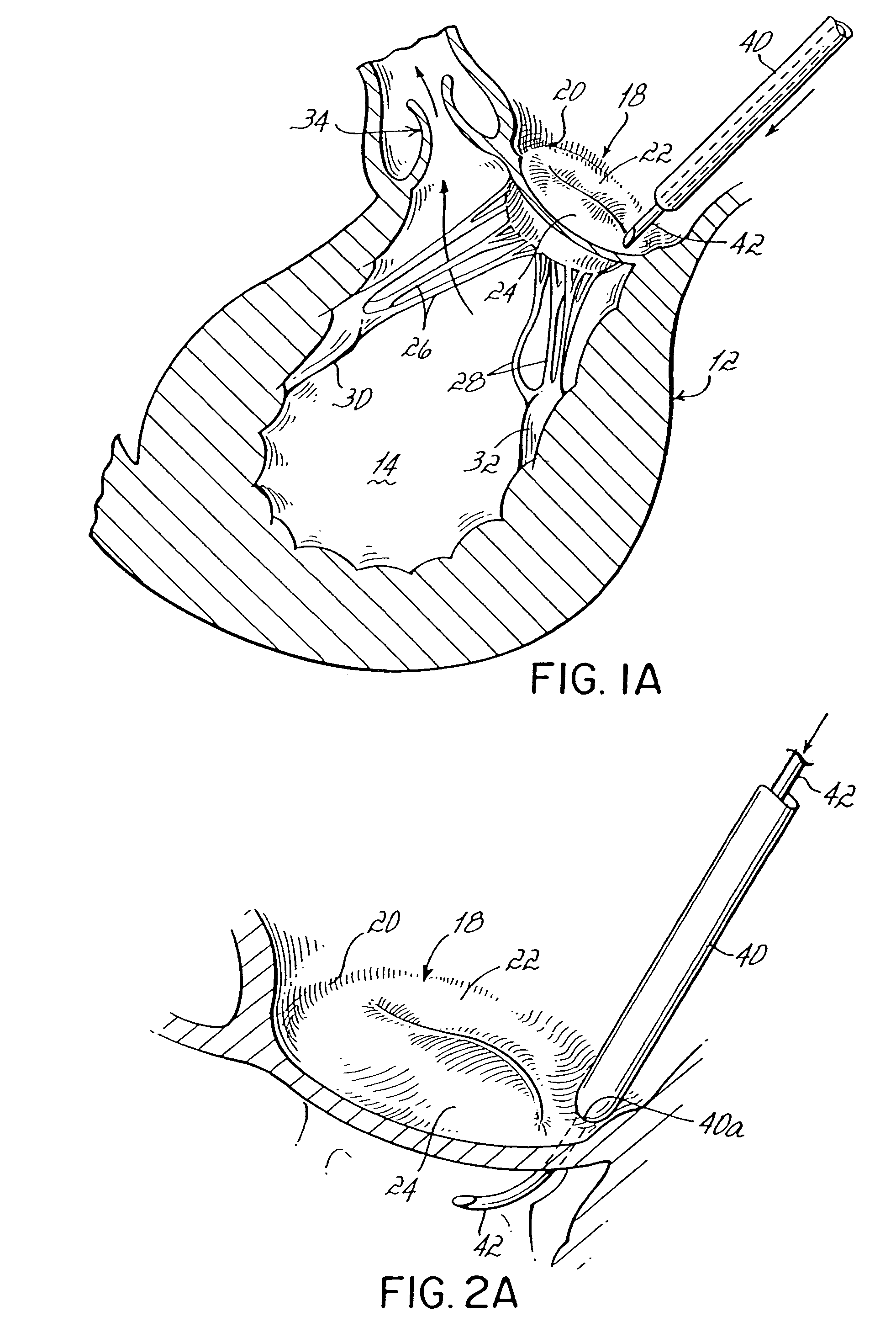
[0069]FIG. 1 illustrates a patient 10 having a heart 12 shown in cross section including a left ventricle 14 and a right ventricle 16. The concepts of the present invention are suitable to be applied, for example, to a mitral valve 18 which supplies blood into left ventricle 14. Mitral valve 18, as better shown in FIG. 1A, includes an annulus 20 and a pair of leaflets 22, 24 which selectively allow and prevent blood flow into left ventricle 14. It will be appreciated that the term annulus tissue is used extensively throughout this disclosure in reference to the drawings, however, the inventive principles are equally applicable when referring to other valve tissue such as leaflet tissue or other attached vessel tissue. Leaflets 22, 24 are supported for coaptation by chordae tendinae or chords 26, 28 extending upwardly from respective papillary muscles 30, 32. Blood enters left ventricle 14 through mitral valve 18 and is expelled during subsequent contraction of heart 12 through aorti...


PUM


Abstract

Devices for repairing and replacing a heart valve in various embodiments, the devices include at least first and second support rings connected together in a coiled configuration to abut opposite sides of a valve annulus. A replacement valve may be secured to the coil-shaped device. Various alternative fastening systems include suture fastening systems, mechanical fastening systems, shape memory alloy fastening systems and other fastening systems relying only on the resilience between adjacent coils. A method generally includes inserting a first end of the coil-shaped member through a valve annulus, rotating a first ring of the coil-shaped member into position on one side of the valve annulus and positioning at least a second ring of the coil-shaped member on an opposite side of the valve annulus.

Description

[0001]This application is a divisional of application Ser. No. 10 / 145,416 filed on May 14, 2002 (now U.S. Pat. No. 6,730,121) which is a divisional of application Ser. No. 09 / 610,784 filed Jul. 6, 2000 (now U.S. Pat. No. 6,419,696), the disclosures of which are fully incorporated herein by reference.FIELD OF THE INVENTION[0002]The present invention generally relates to heart valve repair and replacement techniques and annuloplasty devices. More specifically, the invention relates to the repair and / or replacement of heart valves having various malformations and dysfunctions.BACKGROUND OF THE INVENTION[0003]Diseased mitral and tricuspid valves frequently need replacement or repair. The mitral and tricuspid valve leaflets or supporting chordae may degenerate and weaken or the annulus may dilate leading to valve leak (insufficiency). The leaflets and chords may become calcified and thickened rendering them stenotic (obstructing forward flow). Finally, the valve relies on insertion of th...

Claims


Application Information

Patent Timeline
Patent Type & Authority Patents(United States)
IPC IPC(8): A61F2/24A61F2/00A61B17/00
CPCA61F2/2409A61F2/2445A61F2/2448A61F2/2466A61F2/2427A61F2/2457A61F2210/0033A61F2230/0091A61F2250/006
Inventor ORTIZ, MARKWHEDON, RANDYSPENCE, PAUL A.
Owner MEDTENTIA INT LTD OY
Why Eureka
Try Eureka