Hand sanitizer monitor

a technology of hand sanitizer and monitor, which is applied in the direction of instruments, electric/electromagnetic audible signalling, alarms, etc., can solve the problems of limited teaching and utilization of prior art patents

Active Publication Date: 2015-08-25
HENNIGAN STEPHEN +1
View PDF10 Cites 19 Cited by
  • Summary
  • Abstract
  • Description
  • Claims
  • Application Information

AI Technical Summary

Problems solved by technology

From these prior references it may be seen that these prior art patents are very limited in their ...

Method used


Image

  • Hand sanitizer monitor
  • Hand sanitizer monitor
  • Hand sanitizer monitor

Examples


Embodiment Construction

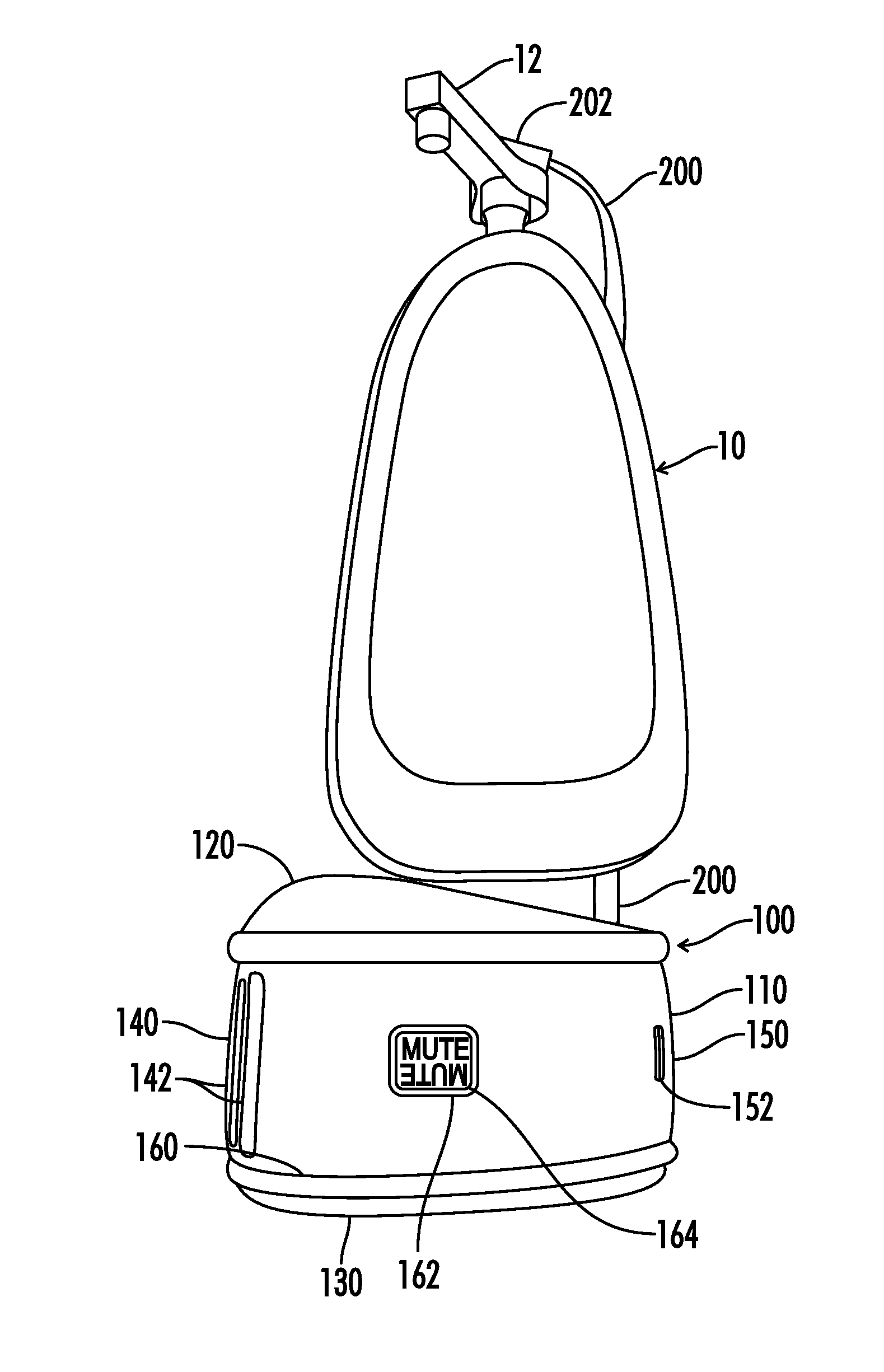
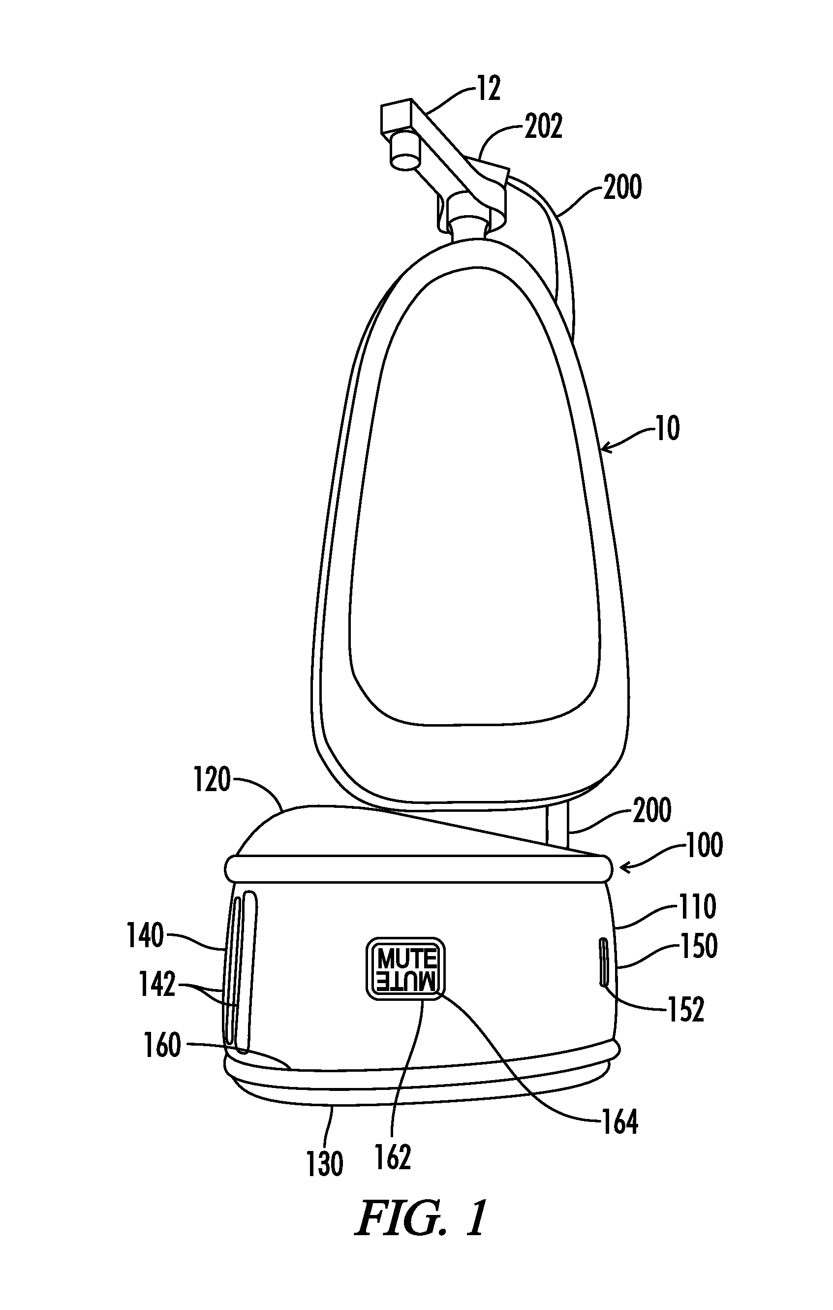
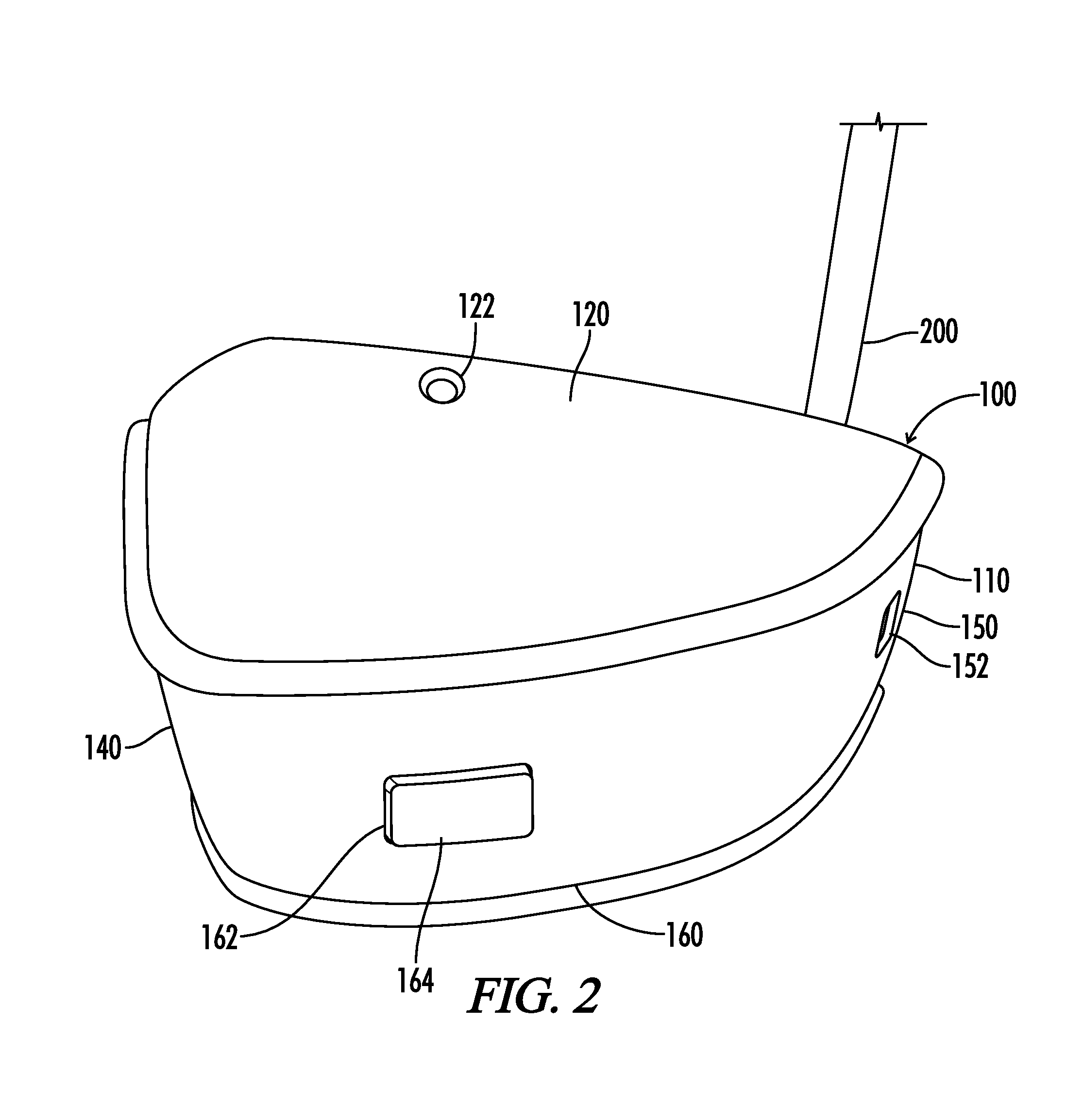
[0024]As shown in FIGS. 1 through 6 of the drawings, one exemplary embodiment of the present invention is generally shown as a hand sanitizer unit 100 for use with a pump bottle 10 having a user activated dispensing pump 12. The hand sanitizer unit 100 is constructed with a main body 110. The main body includes a top 120, bottom 130, left side 140, right side 150, front 160, and back 170. These reference descriptions are being used for describing the item as shown in the drawings, but obviously may change descriptions with a different orientation. The top 120 includes a top mounting aperture 122 and similarly, the bottom 130 also includes a bottom mounting aperture 132 so that screws may be used to secure the unit to a wall, door, or other appropriate mounting location. The left side 140 includes a sensor recess 142 with a sensor aperture 144 used to allow the electrical circuit sensors to detect movement. The right side 150 includes a communications aperture 152 to allow for the un...


PUM


Abstract

A hand sanitizer unit for use with a pump bottle using a user activated dispensing pump with a main body housing an electronic circuit and defining a sensor aperture for use with two passive infrared sensors separated by a mechanical lens baffle to detect movement and direction of the movement. The unit also includes a pump sensor positioned to detect dispensing or lack thereof of a hand sanitizer to sound an alarm when motion is detected and the pump sensor does not detect activation of the user activated dispensing pump. Further items include a mute control switch, communication system, and a direction of motion switch connected to the microprocessor. The programming flow and method of operation of the unit are also disclosed.

Description

CROSS-REFERENCE TO RELATED APPLICATIONS[0001]This application claims priority to and is a continuation-in-part of U.S. Patent Application Ser. No. 61 / 790,454, filed on Mar. 15, 2013 entitled Hand Sanitizer which is hereby incorporated by reference in its entirety.STATEMENT REGARDING FEDERALLY SPONSORED RESEARCH OR DEVELOPMENT[0002]Not Applicable.REFERENCE TO A MICROFICHE APPENDIX[0003]Not Applicable.RESERVATION OF RIGHTS[0004]A portion of the disclosure of this patent document contains material which is subject to intellectual property rights such as but not limited to copyright, trademark, and / or trade dress protection. The owner has no objection to the facsimile reproduction by anyone of the patent document or the patent disclosure as it appears in the Patent and Trademark Office patent files or records but otherwise reserves all rights whatsoever.BACKGROUND OF THE INVENTION[0005]1. Field of the Invention[0006]The present invention relates to improvements in monitoring dispensers ...

Claims


Application Information

Patent Timeline
IPC IPC(8): G08B23/00G08B21/24
CPCG08B21/245G08B3/10
Inventor HENNIGAN, STEPHENRATZ, DAVID
Owner HENNIGAN STEPHEN
Why Eureka
Try Eureka