
Image forming apparatus

a technology of image forming apparatus and electrograph, which is applied in the direction of electrograph process apparatus, instruments, optics, etc., can solve the problem of requiring a long time to elaps

Inactive Publication Date: 2015-09-01
BROTHER KOGYO KK
View PDF4 Cites 0 Cited by
  • Summary
  • Abstract
  • Description
  • Claims
  • Application Information

AI Technical Summary

Benefits of technology

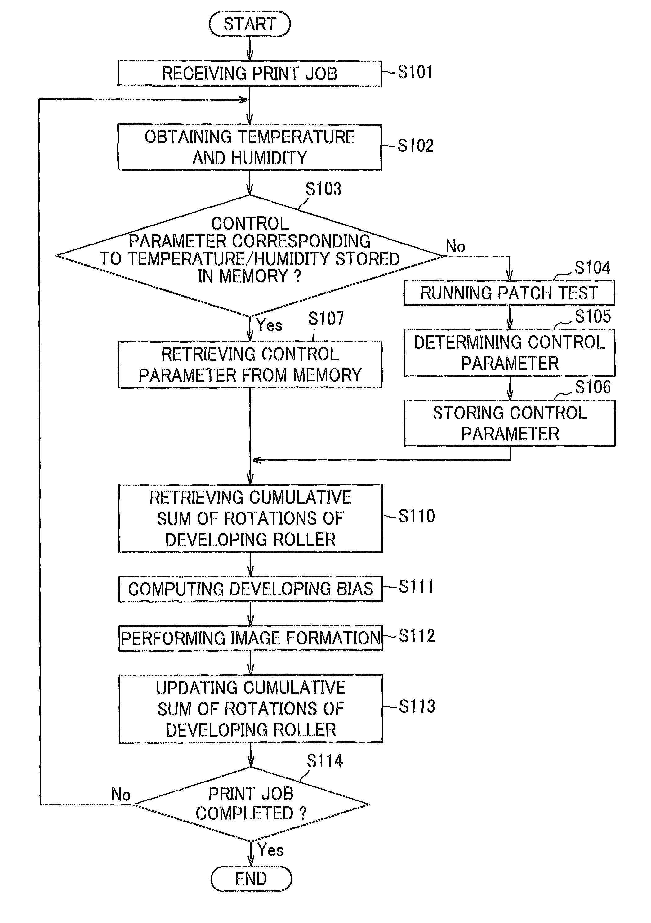
[0007]It is one aspect of the present invention to provide an image forming apparatus with quick print start capability which may be achieved by decreasing the frequency of test prints (test-mode processes).

Problems solved by technology

The test print performed every time when the surrounding conditions change would disadvantageously require a long time to elapse before starting the printing.

Method used


Image

  • Image forming apparatus
  • Image forming apparatus
  • Image forming apparatus

Examples


Embodiment Construction

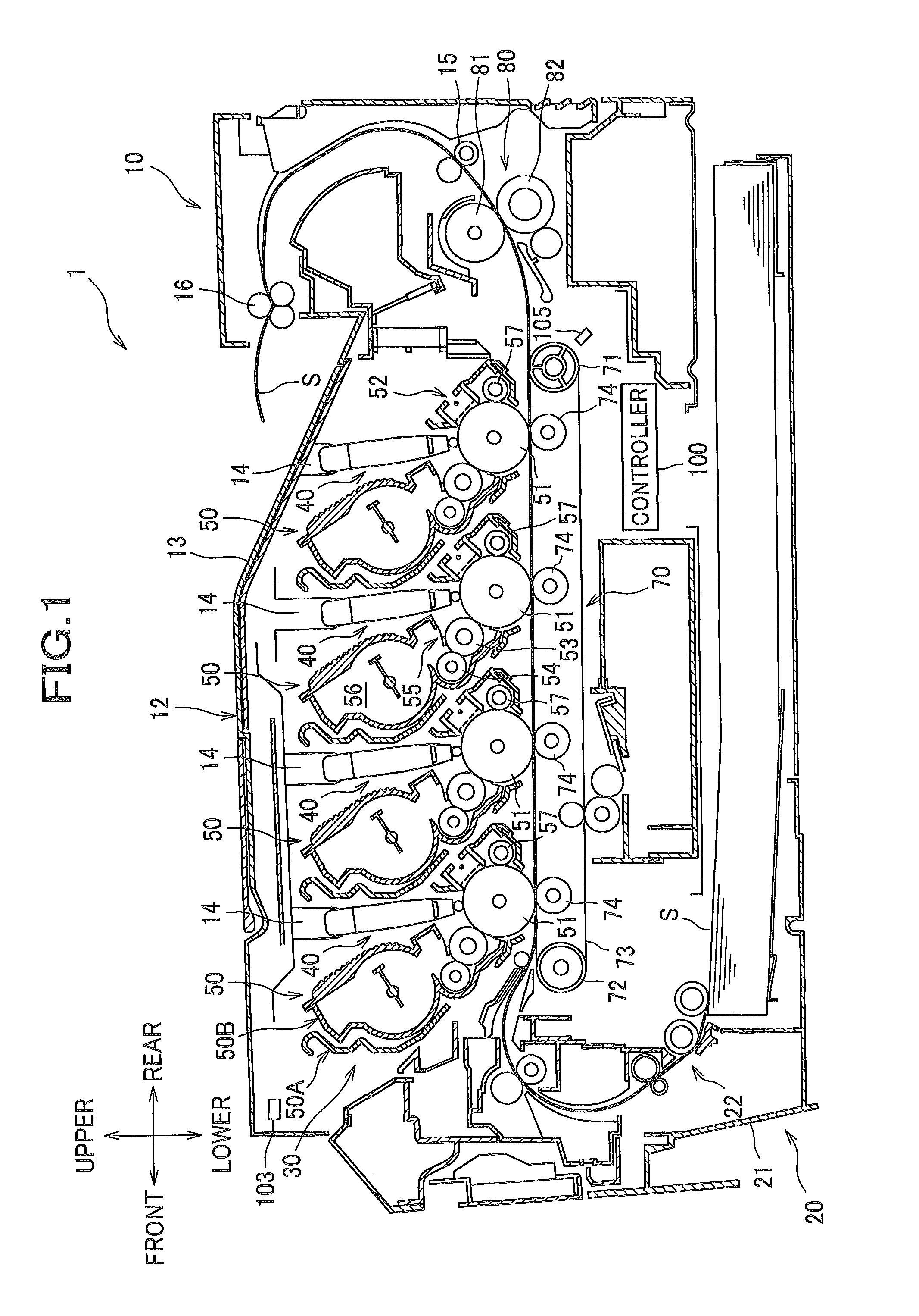
[0023]A detailed description will be given of an illustrative, non-limiting embodiment of the present invention with reference made to the drawings where appropriate. In the following description, the direction is designated as from the viewpoint of a user who is using (operating) the color printer 1. To be more specific, in FIG. 1, the left-hand side of the drawing sheet corresponds to the “front” side of the printer, the right-hand side of the drawing sheet corresponds to the “rear” side of the printer, the front side of the drawing sheet corresponds to the “right” side of the printer, and the back side of the drawing sheet corresponds to the “left” side of the printer. Similarly, the direction of a line extending from top to bottom of the drawing sheet corresponds to the “vertical” or “up / down (upper / lower or top / bottom)” direction of the printer.

[0024]As shown in FIG. 1, the color printer 1 comprises a main body housing 10, and several components housed within the main body hous...


PUM


Abstract

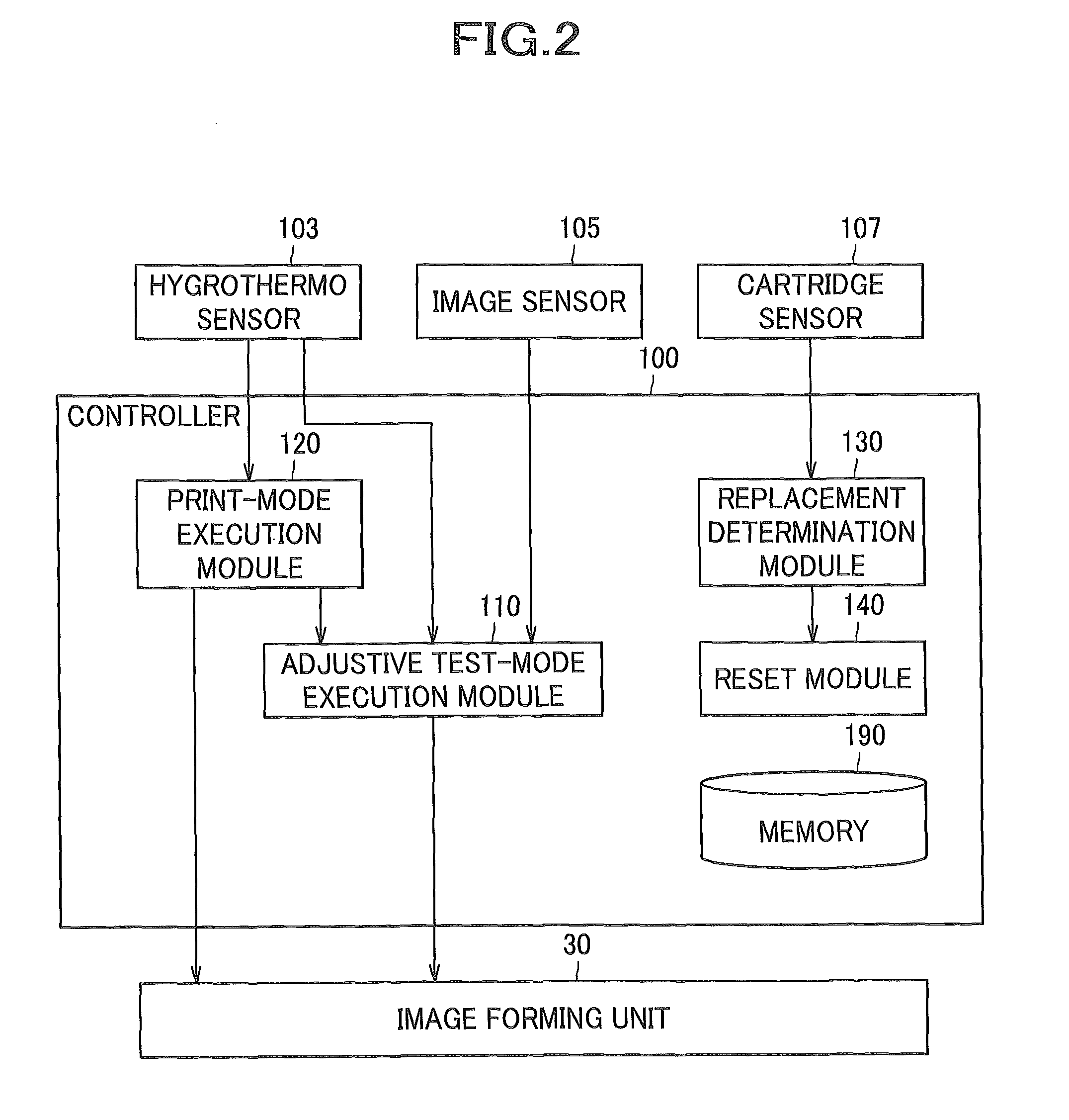
In an image forming apparatus, a controller includes a memory stores control parameters for use in adjustment to be made in at least one of a print density and a color alignment in accordance with a surrounding condition, a print-mode execution module executes a print-mode process of causing the image forming unit to perform image formation, and an adjustive test-mode execution module executes an adjustive test-mode process of causing the image forming unit to perform a test print, thereby determining a control parameter. The print-mode execution module retrieves a relevant control parameter corresponding to a current surrounding condition from the memory, if available, while it causes the adjustive test-mode execution module to execute the adjustive test-mode process, thereby determining a relevant control parameter if the relevant control parameter is not stored in the memory. The retrieved or determined relevant control parameter is applied to the image formation.

Description

CROSS-REFERENCE TO RELATED APPLICATION(S)[0001]This application claims priority from Japanese Patent Application No. 2013-150025 filed on Jul. 19, 2013, the disclosure of which is incorporated herein by reference in its entirety.BACKGROUND[0002]1. Field[0003]The present invention relates to an electrophotographic image forming apparatus.[0004]2. Description of Related Art[0005]In the electrophotographic image forming apparatus, the print density varies according to the surrounding conditions such as temperature, humidity and the like. In the image forming apparatus which performs color printing, in particular, the pixel position of each color shifts according to the temperature. Therefore, in these types of image forming apparatus, typically, the test print is performed every time when the surrounding conditions change, and a control parameter for use in adjustment to be made in the print density or color alignment (registration) is determined based upon the result of the test print...

Claims


Application Information

Patent Timeline
Patent Type & Authority Patents(United States)
IPC IPC(8): G03G15/00
CPCG03G15/50G03G15/5058G03G15/55G03G21/203
Inventor MATSUSHITA, YUICHI
Owner BROTHER KOGYO KK
Learn More