
Hybrid power transmission system with energy storage and distribution

A technology of hybrid power and transmission system, which is applied in transmission devices, belts/chains/gears, mechanical equipment, etc. It can solve problems such as inability to deploy, increase equipment, increase costs, etc., and achieve the effect of quick start

Inactive Publication Date: 2021-01-29
广州东谦科技有限公司
View PDF0 Cites 0 Cited by
  • Summary
  • Abstract
  • Description
  • Claims
  • Application Information

AI Technical Summary

Problems solved by technology

[0003] Under the existing technology, most of the transmissions are only fixed-ratio and fixed-speed transmissions through gear sets. Power fluctuations at the input end or load fluctuations at the output end will lead to unstable operation of the machine. Some machines require high precision, so by fully increasing the rated input end Power to fully meet the power demand of the load end. When one input end and multiple output ends are involved, the rated power needs to be raised higher. The input end can be an active machine such as a motor or a diesel engine. The increase in power will inevitably lead to an increase in device size and cost. , and it cannot be adjusted according to the load ratio of the output terminal

Method used


Image

  • Hybrid power transmission system with energy storage and distribution
  • Hybrid power transmission system with energy storage and distribution
  • Hybrid power transmission system with energy storage and distribution

Examples


Embodiment Construction

[0032]The following will clearly and completely describe the technical solutions in the embodiments of the present invention with reference to the accompanying drawings in the embodiments of the present invention. Obviously, the described embodiments are only some, not all, embodiments of the present invention. Based on the embodiments of the present invention, all other embodiments obtained by persons of ordinary skill in the art without making creative efforts belong to the protection scope of the present invention.

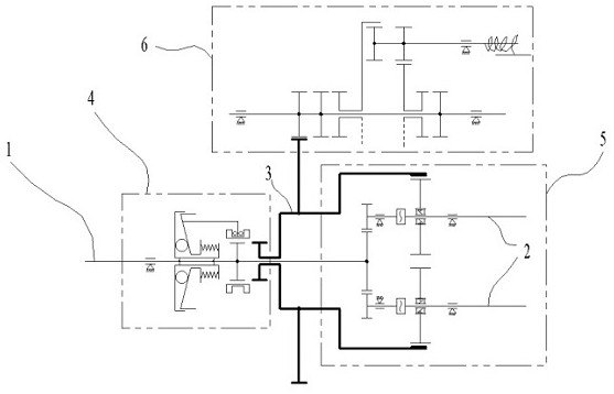
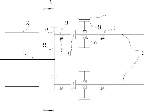
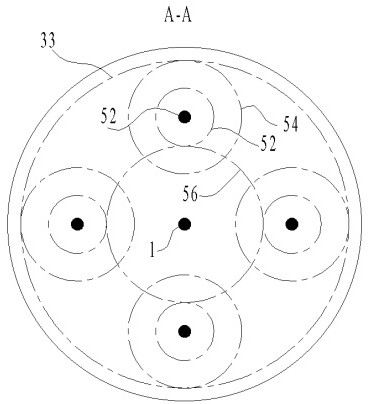
[0033] like figure 1 , 2 , 4, a hybrid power transmission system with energy storage and distribution, including input shaft 1, output shaft 2, flywheel 3, escape assembly 4 and sub-shaft assembly 5, flywheel 3, escape assembly 4 are installed on On the input shaft 1, the escape assembly 4 drives and connects the flywheel 3 and the input shaft 1 after the input shaft 1 exceeds the rated speed. At least a fluid coupler 53 is provided on the connection path bet...


PUM


Abstract

The invention discloses a hybrid power transmission system with energy storage and distribution, which comprises an input shaft, an output shaft, a flywheel, a speed escape assembly and a split shaftassembly, wherein the flywheel and the speed escape assembly are arranged on the input shaft, and the flywheel and the input shaft are in transmission connection together by the speed escape assemblyafter the input shaft exceeds a rated rotation speed; the split shaft assembly comprises a hydraulic coupler, a speed taking gear, an overrunning clutch, a plurality of auxiliary shafts, auxiliary gears and a main shaft gear, at least the hydraulic coupler is arranged on a connecting passage of the input shaft and the output shaft, the output shaft is connected to the speed taking gear through theoverrunning clutch, the flywheel comprises a flywheel body and a flywheel inner gear, and the flywheel body is installed with the input shaft as the axis; the flywheel inner gear is arranged on the side, close to the output shaft, of the wheel body, and the speed taking gear is meshed with the flywheel inner gear; the main shaft gear is arranged at one end of the input shaft, the auxiliary shaftsare distributed along the circumference of the input shaft, and one end of each auxiliary shaft is provided with an auxiliary gear meshed with the main shaft gear.

Description

technical field [0001] The invention relates to the field of transmission devices, in particular to a hybrid power transmission system with energy storage and distribution. Background technique [0002] The transmission system exists in most machines and mechanical devices. [0003] Under the existing technology, most of the transmissions are only fixed-ratio and fixed-speed transmissions through gear sets. Power fluctuations at the input end or load fluctuations at the output end will lead to unstable operation of the machine. Some machines require high precision, so by fully increasing the rated input end Power to fully meet the power demand of the load end. When one input end and multiple output ends are involved, the rated power needs to be raised higher. The input end can be an active machine such as a motor or a diesel engine. The increase in power will inevitably lead to an increase in device size and cost. , and it cannot be adjusted according to the load ratio of t...

Claims


Application Information

Patent Timeline
Patent Type & Authority Applications(China)
IPC IPC(8): F16H33/06F16H35/00
CPCF16H33/06F16H35/00
Inventor 李雪
Owner 广州东谦科技有限公司
Learn More