
Rechargeable personal massager

a rechargeable, personal massager technology, applied in the field of massagers, can solve the problems of limited time of operation, inconvenience, environmental impact, and expense of necessary battery replacement, and achieve the effect of keeping the device stabl

Active Publication Date: 2015-09-15
LELO
View PDF130 Cites 58 Cited by
  • Summary
  • Abstract
  • Description
  • Claims
  • Application Information

AI Technical Summary

Benefits of technology

The solution provides extended operational time, improved safety, enhanced waterproofing, and user customization, enabling safe and effective use in damp conditions while eliminating the need for battery replacement and reducing environmental impact.

Problems solved by technology

It will be apparent to the reader that this type of battery operation has drawbacks, including for example, limited time of operation, the inconvenience, expense, and environmental impact associated with the necessary battery replacement, and the difficulty of creating a reliable waterproof seal around a user operated moving part such as a battery door.
While some vibrating massagers operate on AC power, for example U.S. 110V or European 220V power, these massagers tend to be large and unsafe for internal use or use in damp environments.
They also have the inconvenience of requiring proximity to a wall plug.
The metal connectors and their receptacles often collect unsanitary residue, are difficult to clean and are subject to corrosion.
Further, such jacks are difficult to waterproof reliably.
Further, such devices require care from the user to ensure proper alignment and contact.
Rechargeable massagers generally use a built-in female plug, engageable with a male plug for recharging, that is difficult to waterproof.
This can harm the charger or the massager, and can potentially be hazardous for the user as well.
A few waterproof products on the market can be warmed by immersing them in hot water, but this can be inconvenient for the user.

Method used


Image

  • Rechargeable personal massager
  • Rechargeable personal massager
  • Rechargeable personal massager

Examples


Embodiment Construction

considered in conjunction with the drawing figures, in which:

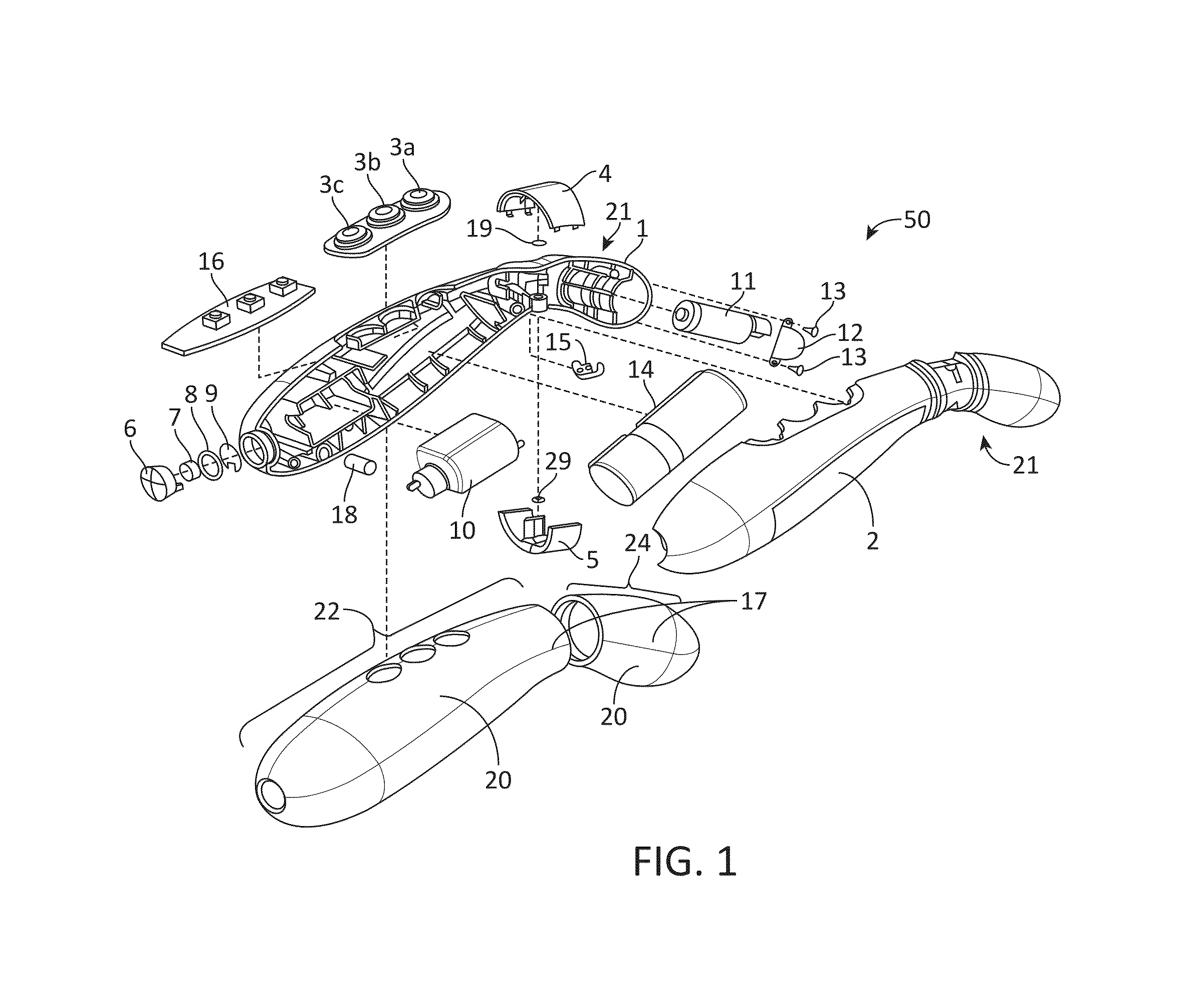
[0023]FIG. 1 is an exploded view of a massager in accordance with one embodiment of the present invention;

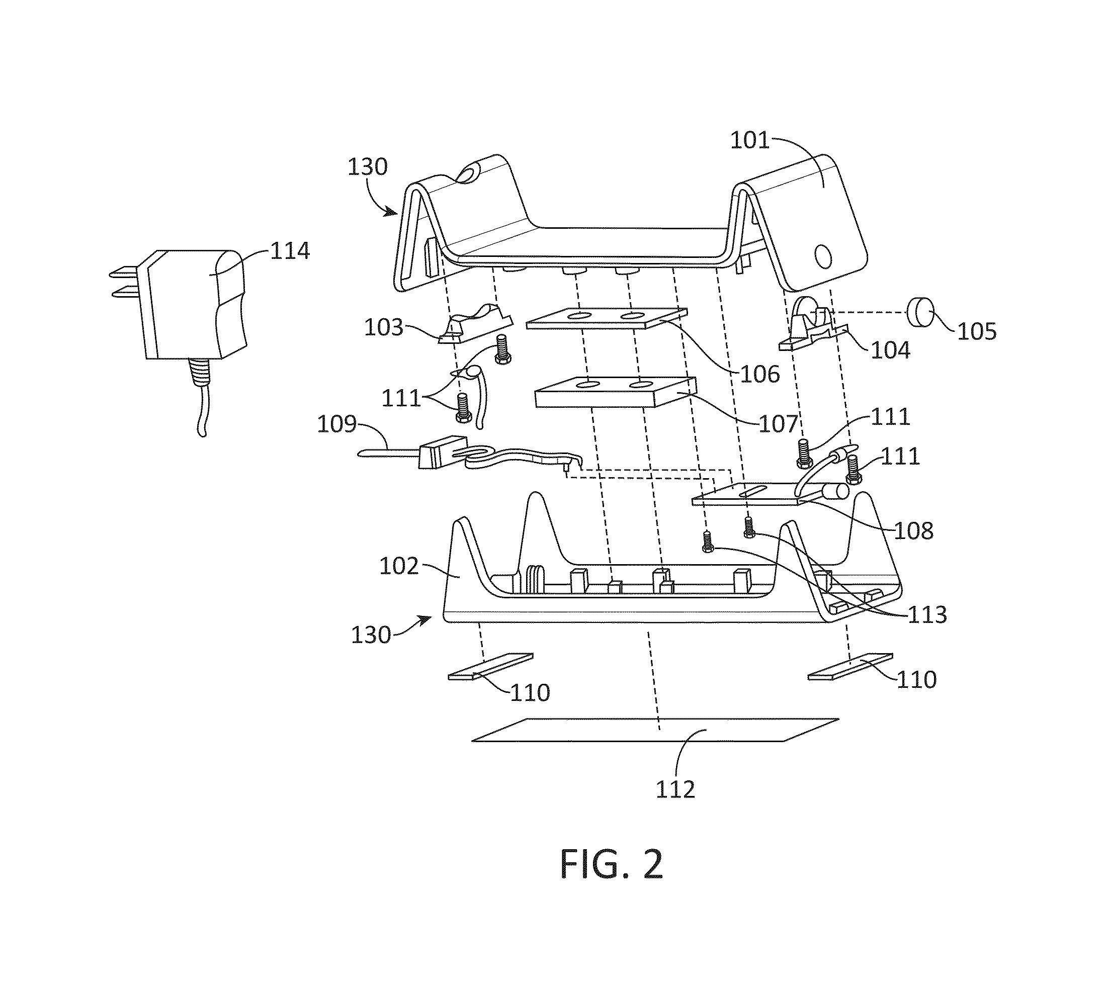
[0024]FIG. 2 is an exploded view of a base for supporting and charging the massager of FIG. 1 in accordance with one embodiment of the present invention;

[0025]FIG. 3 is a block diagram illustrating the various electronic components of the massager of FIG. 1, with optional components indicated by a broken line;

[0026]FIG. 4 is a schematic view of an electronic circuit used in the base of FIG. 2;

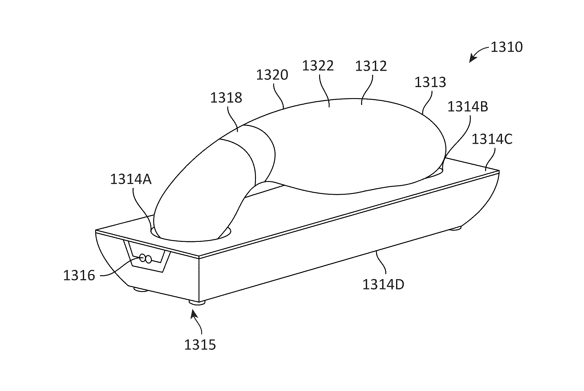
[0027]FIGS. 5A, 5B, 5C and 5D are top, right side, front end and back end views of the massager of FIG. 1 situated in the base of FIG. 2, respectively;

[0028]FIG. 6 is a perspective view of the massager of FIG. 1 situated in the base of FIG. 2;

[0029]FIGS. 7A and 7B are front and rear side perspective views of the massager of FIG. 1, including the electrical contacts for mating with electrical contacts on the base;

[0030]FIG. 8 is a ...


PUM


Abstract

A personal massage device is disclosed. The massage device includes a housing having an exterior surface defining first and second oppositely-disposed operative ends and an interior surface defining a cavity. Each of the operative ends includes a substantially smooth and continuous surface thereon. The massage device further includes a first motor disposed within the housing and adapted for creating vibration and a battery disposed within the housing and adapted to power the first motor.

Description

CROSS-REFERENCE TO RELATED APPLICATIONS[0001]This application is a continuation-in-part of U.S. patent application Ser. No. 11 / 344,987, filed on Feb. 1, 2006, now U.S. Pat. No. 7,749,178, issued Jul. 6, 2010, which is incorporated by reference herein in its entirety. This application also claims the benefit of U.S. Provisional Patent Application No. 60 / 879,440, filed on Jan. 9, 2007, which is incorporated by reference herein in its entirety.BACKGROUND[0002]The present invention relates generally to massagers and more particularly to rechargeable personal massagers, methods, and apparatuses.[0003]Personal vibrators, also known variously as vibrators, massagers, vibrating massagers and by numerous other names, are well-known in the art. They come in a variety of configurations and perform a variety of functions, ranging from medical therapy to erotic stimulation. They typically are battery-powered or run on conventional alternating current electricity.[0004]Vibrating massagers powered...

Claims


Application Information

Patent Timeline
Patent Type & Authority Patents(United States)
IPC IPC(8): A61H1/00A61H19/00A61H23/02
CPCA61H19/00A61H19/40A61H23/0263A61H2201/0111A61H2201/0153A61H2201/0115A61H2230/425A61H2230/255A61H7/005A61H21/00A61H39/002A61H2201/0134A61H2201/0149A61H2201/0207A61H2201/0221A61H2201/0228A61H2201/0278A61H2201/0292A61H2201/1609A61H2201/1623A61H2201/164A61H2201/169A61H2201/5005A61H2201/501A61H2201/5015A61H2201/5064A61H2201/5084A61H2201/5097A61H2205/04A61H2205/081A61H2205/12A61H2230/06A61H2230/065A61H2230/105A61H2230/505A61H2230/605A61H2230/655A63B2225/66A61H23/006H02J7/0044H02J50/10H02J50/12
Inventor IMBODEN, ETHAN F.WYATT, ROLAND J.
Owner LELO
Learn More