Device for distributing bulk material with a distribution spout supported by a cardan suspension

a technology of distribution spout and distribution suspension, which is applied in the direction of charge manipulation, lighting and heating apparatus, furnaces, etc., can solve the problems of inherently subject to a certain degree of actuator outage and repair, and achieve the effect of more reliabl

Active Publication Date: 2015-09-15
PAUL WURTH SA
View PDF19 Cites 4 Cited by
  • Summary
  • Abstract
  • Description
  • Claims
  • Application Information

AI Technical Summary

Benefits of technology

[0007]In view of the foregoing, the present disclosure provides a distribution device that has a cardan-type spout suspension with comparatively low moment of inertia and a more reliable drive arrangement.
[0012]As will be understood, the use of a rotary motor as an actuator allows charging typical ring-shaped or spiral patterns without the need for a constantly reciprocating motion of linear actuators. Accordingly, due to the typically high availability of rotary drives i.e. due to their inherent reliability, the proposed construction is less subject to actuator outage and therefore more reliable than prior art devices as proposed in JP 58 207303 or EP 1 833 999.

Problems solved by technology

A drawback of designs according to JP 58 207303 and EP 1 833 999 resides in the actuators used in their drive arrangement.
As a result, a device according to JP 58 207303 and EP 1 833 999 is inherently subject to a certain degree of actuator outage and consequent repair.

Method used


Image

  • Device for distributing bulk material with a distribution spout supported by a cardan suspension
  • Device for distributing bulk material with a distribution spout supported by a cardan suspension
  • Device for distributing bulk material with a distribution spout supported by a cardan suspension

Examples


first embodiment

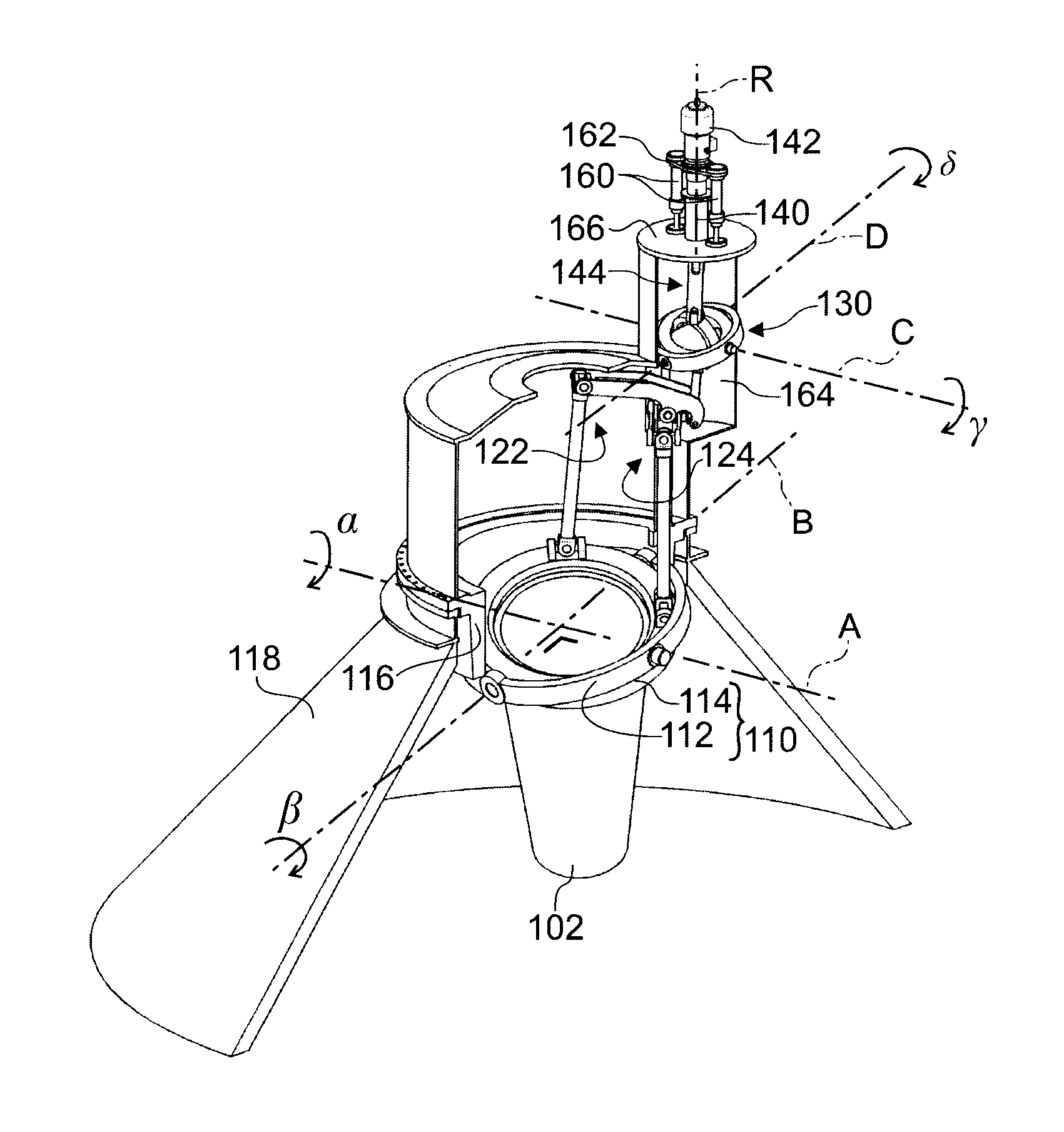
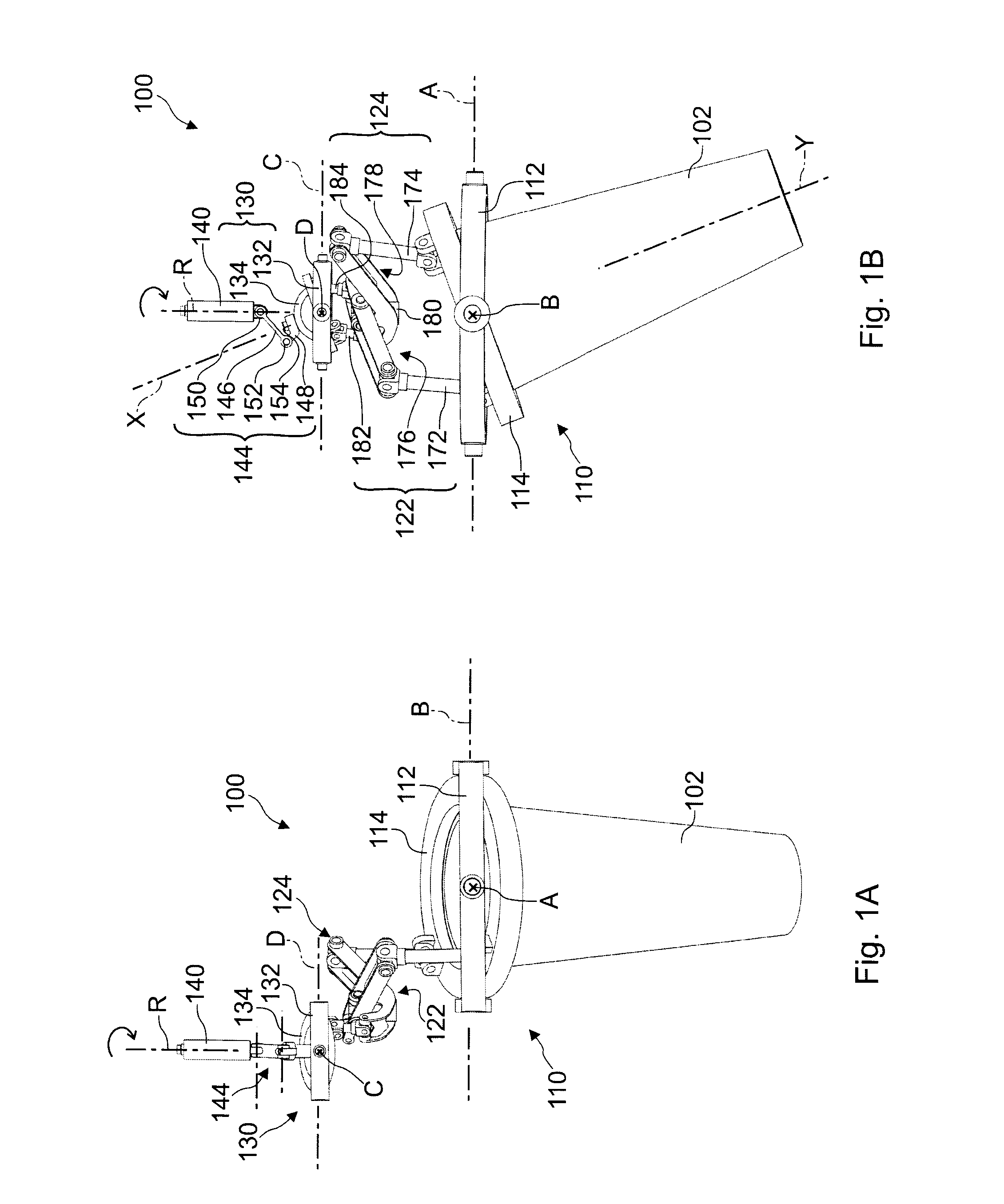
[0020]FIGS. 1A&1B illustrate a distribution device, generally identified by reference numeral 100. The device 100 includes a distribution spout 102 of tubular shape, e.g. with a chute body having a frustoconical envelope. The distribution spout 102 is supported by means of a cardan suspension 110 that includes an outer first gimbal member 112 and an inner second gimbal member 114. In the illustrated embodiment, both gimbal members 112, 114 are annular gimbal rings. By virtue of the cardan suspension 110, the outlet of the spout 102 can be oriented as desired in any direction to direct the flow of bulk charge material to any desired point of a charging surface inside the reactor.

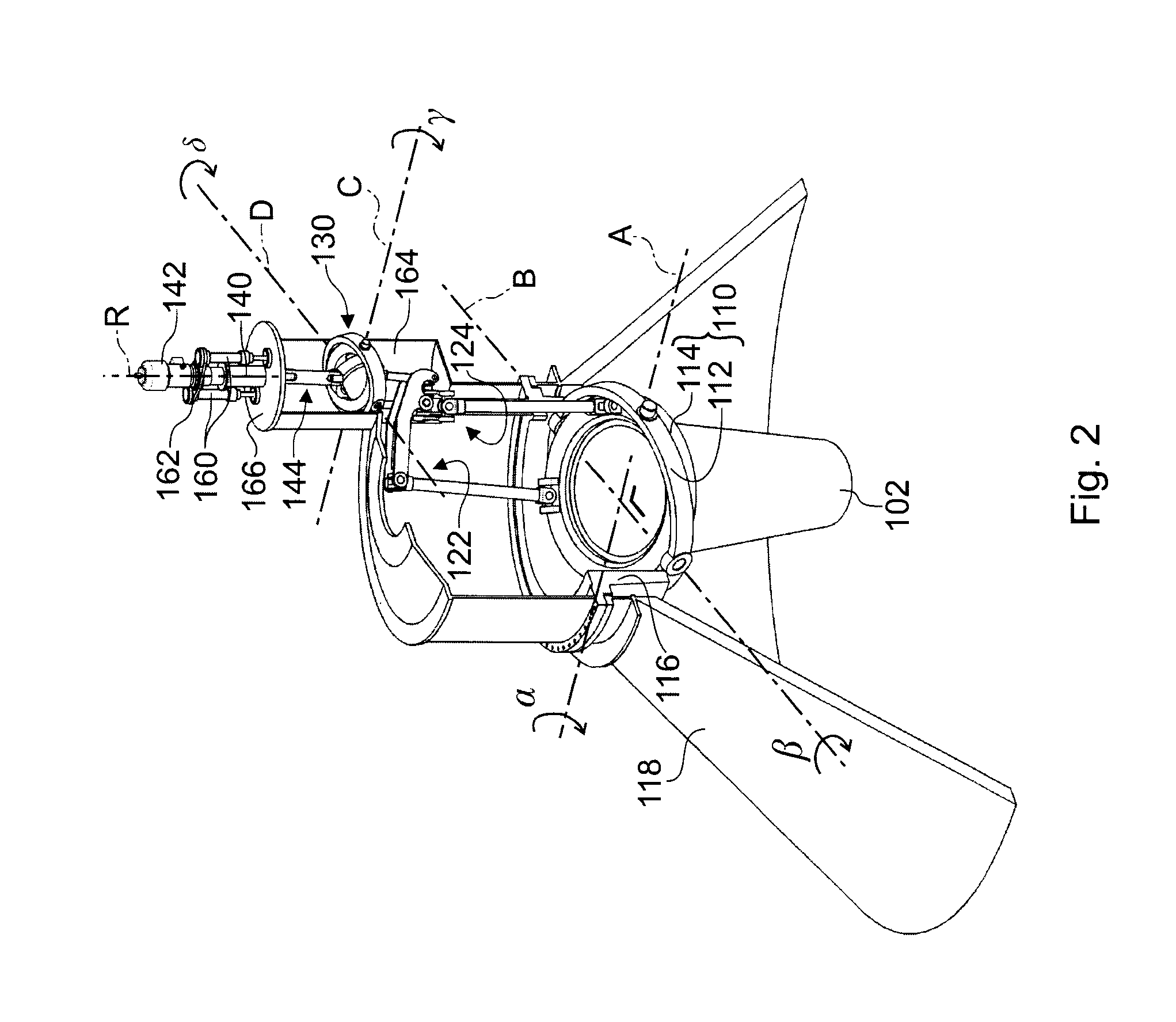
[0021]As best seen in FIG. 2, the outer gimbal member 112 has diagonally opposite pivots by means of which it is pivotally supported on an annular supporting structure 116 that is fixed inside a top part 118 of the metallurgical reactor (not shown in full), e.g. of a blast furnace throat. Accordingly, the fir...

third embodiment

[0031]FIGS. 4A&4B illustrate a distribution device 300 in accordance with the invention. In the distribution device 300, as opposed to the previous embodiments, the rotary drive shaft 340 has a horizontal axis R. Therefore, the cardan joint 330 that replicates the cardan suspension 310 is generally rotated by 90°. In other words, the pivotal axis D of the second part 334 forms a right angle with respect to the corresponding pivotal axis B of the second gimbal member 314. Thus, when the chute 302 is oriented vertically, the pivotal axis D is vertical (as opposed to horizontal in FIGS. 1A&1B) and the main axis X of the second part 334 is horizontal (as opposed to vertical in FIGS. 1A&1B) to be aligned with the axis R of the rotary drive shaft 340. Consequently, the transmission mechanisms 322, 324 of the device 300 have yet another configuration. Whilst they are symmetrical, their pivoted levers 376, 378 are elbowed, more specifically, they are arranged with their short lever arm bein...

fourth embodiment

[0032]FIG. 5 schematically illustrates an alternative fourth embodiment of a distribution device 400 with a cardan suspended spout and an auxiliary cardan joint 430 driven by an axially slideable rotary drive shaft 440. In the device 400, the transmission mechanisms 422, 424 that link the cardan joint 430 to the cardan suspension 410 of the spout (not shown in FIG. 5) have yet another different configuration compared to the previous embodiments.

[0033]The first transmission mechanism 422 connects the outer gimbal member 412 to the outer first part 432 of the cardan joint 430. To this effect, it has pivotal shaft 492 with an output crank arm 493 fixed at a right angle to the pivotal shaft 492. An output connecting rod 472 with universal joints connects the output crank arm 493 to the first gimbal member 412. In similar manner, the pivotal shaft 492 has an input crank arm 483 articulated to the first part 432 of the cardan joint 430 by means of an input connecting rod 482. For increasi...


PUM

PropertyMeasurementUnit
angleaaaaaaaaaa
torqueaaaaaaaaaa
transmission ratioaaaaaaaaaa

Abstract

A distribution device for distributing bulk material with a distribution spout on a cardan suspension that has a first and a second gimbal member pivotable about two perpendicular suspension axes where a drive arrangement has a first and a second transmission mechanism for controlling pivotal motion of the distribution spout about the suspension axes, and the drive arrangement has a further cardan joint, with a first part pivotable about a third axis and a second part pivotable about a fourth axis, and a rotary motor for driving a rotary drive shaft that is connected to the cardan joint by means of an articulated connecting arm such that the rotational position and the axial position of the drive shaft determine the pivotal position of the second part about the third and fourth axes respectively, where the transmission mechanisms transmit torque about the third and fourth axes from the cardan joint to the cardan suspension for pivoting the distribution spout about the first and second axes respectively.

Description

TECHNICAL FIELD[0001]The present invention generally relates to charging of material into a metallurgical reactor, e.g. a melter-gasifier, an aggregate reactor or a blast furnace. More specifically, the invention relates to a device for distributing charge material within the metallurgical reactor.BACKGROUND ART[0002]The distribution device is a key component of any typical top charging installation because proper charge distribution is crucial for reactor operation.[0003]In the iron-making industry, a charging system commercially known by the name bell less Top® has found widespread use for charging blast furnaces. This system typically includes a distribution device with a distribution chute that is rotatable about the vertical furnace axis and pivotable about a horizontal axis for distributing bulk material on the stockline as desired. The device has a mechanism for rotating and pivoting the distribution chute according to the desired charging profile. Systems of this type have b...

Claims


Application Information

Patent Timeline
Patent Type & Authority Patents(United States)
IPC IPC(8): C21B7/20F27B1/20F27D3/10
CPCC21B7/20F27B1/20F27D3/10F27D2003/0046
Inventor THILLEN, GUYLONARDI, EMILESTUMPER, JEAN-JOSEPHLANG, HARALDMUTSCHLER, KLAUS
Owner PAUL WURTH SA
Why Eureka
Try Eureka