Turbine de-swirl elements

a technology of turbines and elements, applied in the direction of combustion engines, machines/engines, stators, etc., can solve the problem of increasing the potential that oil from the bearing housing could leak into the turbine housing

Inactive Publication Date: 2018-09-27
GARRETT TRANSPORATION I INC
View PDF1 Cites 2 Cited by
  • Summary
  • Abstract
  • Description
  • Claims
  • Application Information

AI Technical Summary

Benefits of technology

[0013]Advantageously, the invention includes one or more de-swirl elements extending through the turbine-wheel back-disk cavity, the de-swirl elements being sized, shaped and located within the turbine-wheel back-disk cavity to impede the circumferential flow of exhaust gas within the turbine-wheel back-disk cavity. These de-swirl elements significantly reduce the circumferential flow of the exhaust gas stream within the turbine-wheel back-disk cavi...

Problems solved by technology

Nevertheless, the low static pressure at the downstream end of the scroll passageway i...

Method used


Image

  • Turbine de-swirl elements
  • Turbine de-swirl elements
  • Turbine de-swirl elements

Examples


Embodiment Construction

[0022]The invention summarized above and defined by the enumerated claims may be better understood by referring to the following detailed description, which should be read with the accompanying drawings. This detailed description of particular preferred embodiments of the invention, set out below to enable one to build and use particular implementations of the invention, is not intended to limit the enumerated claims, but rather, it is intended to provide particular examples of them.

[0023]Typical embodiments of the present invention reside in a motor vehicle equipped with a gasoline powered internal combustion engine and a turbocharger. The turbocharger is equipped with unique elements that may reduce the likelihood of oil leakage from a bearing housing into a turbine.

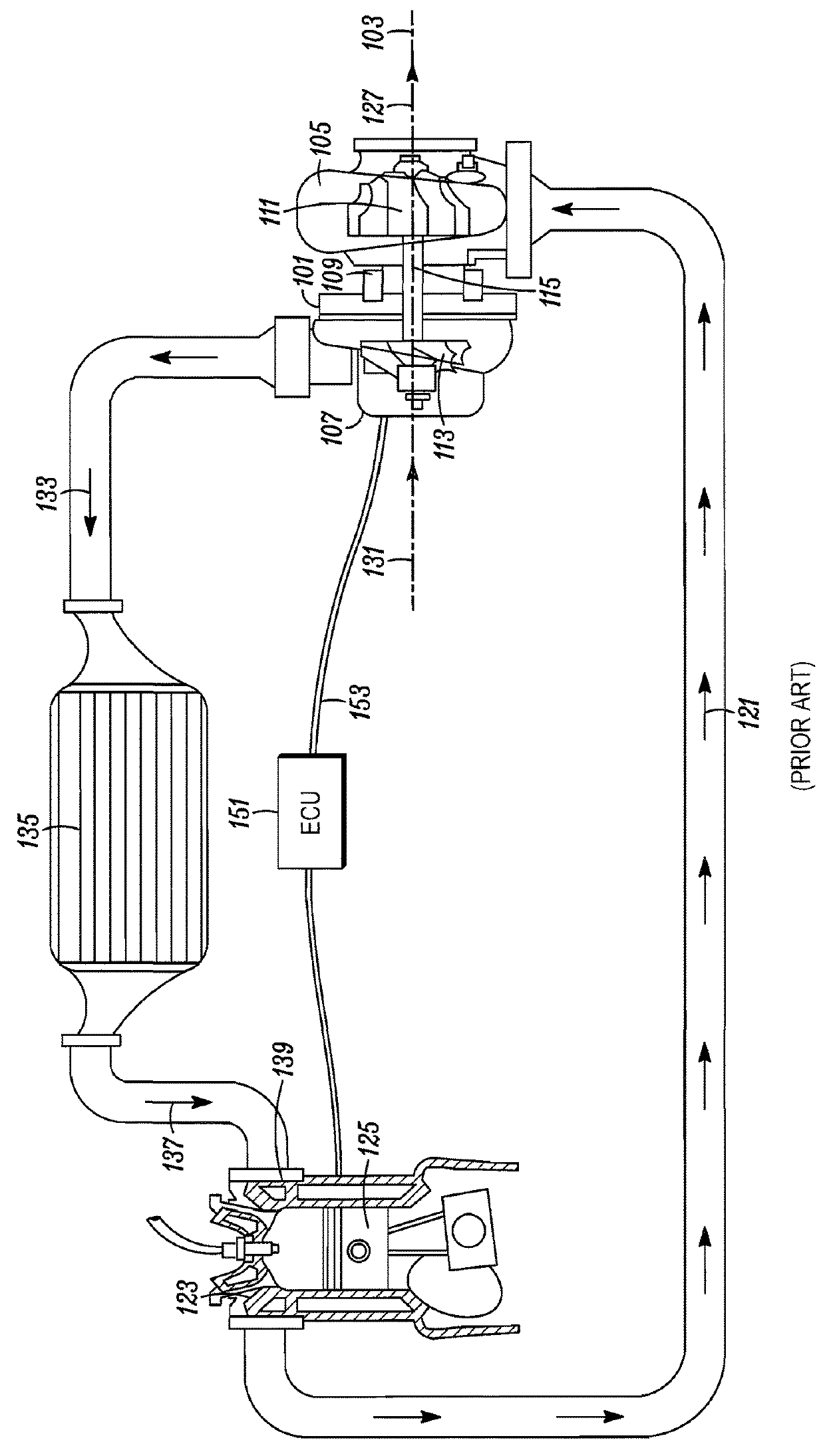
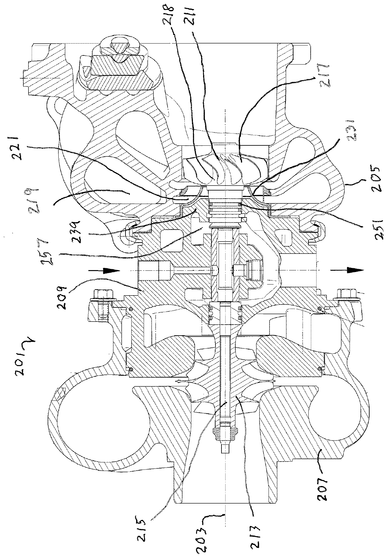
[0024]With reference to FIG. 2, in a first embodiment of the invention a typical internal combustion engine and ECU (and optionally an intercooler), such as are depicted in FIG. 1, are provided with a turbocharger 201 ...


PUM


Abstract

A turbocharger including a turbocharger housing, a rotor and a heat shroud. The turbocharger housing includes a turbine housing affixed to a bearing housing. The rotor includes an axial turbine wheel with a hub, and a shaft extending through the bearing housing. The hub defines a back-disk surface that faces the bearing housing, and the bearing-housing defines an outer surface facing the turbine hub. The turbine housing forms a radial scroll, and the heat shroud forms a curved portion turning that radial scroll direction to an axial direction. The heat shroud establishes a back-disk cavity between a bearing-housing turbine-end-wall outer surface, the turbine-wheel back-disk surface, the curved portion of the heat shroud, and a cylindrical outer surface of a turbine-end portion of the shaft. The heat shroud includes flat ribs within the back-disk cavity to impede the circumferential flow of exhaust gas within the back-disk cavity.

Description

[0001]The present invention relates generally to turbochargers and, more particularly, to an axial turbine having elements to minimize oil leakage from the bearings into the turbine.BACKGROUND OF THE INVENTION[0002]With reference to FIG. 1, a typical turbocharger 101 has a turbine that includes a turbocharger housing and a rotor configured to rotate within the turbocharger housing around an axis of rotor rotation 103 on oil-lubricated thrust bearings and two sets of oil-lubricated journal bearings (one for each respective rotor wheel), or alternatively, other similarly supportive bearings. The turbocharger housing includes a turbine housing 105, a compressor housing 107, and a bearing housing 109 (i.e., a center housing that contains the bearings) that connects the turbine housing to the compressor housing. The rotor includes a turbine wheel 111 located substantially within the turbine housing, a compressor wheel 113 located substantially within the compressor housing, and a shaft 1...

Claims


Application Information

Patent Timeline
IPC IPC(8): F02B37/00
CPCF02B37/00F01D5/048F01D9/02F01D25/08F01D25/16F01D25/24F05D2220/40F01D5/046F01D9/048Y02T10/12
Inventor BABAK, MARTIN
Owner GARRETT TRANSPORATION I INC
Why Eureka
Try Eureka