

Apparatus and method for preparing aminobenzene by nitrobenzene gas-phase hydrogenation
A technology for the preparation of nitrobenzene gas and hydrogen, which is applied in the preparation of amino compounds, chemical instruments and methods, preparation of organic compounds, etc., to achieve the effects of reducing dosage, increasing safety, and reducing investment costs
- Summary
- Abstract
- Description
- Claims
- Application Information
AI Technical Summary
Problems solved by technology
Method used
Image

Examples
preparation example Construction
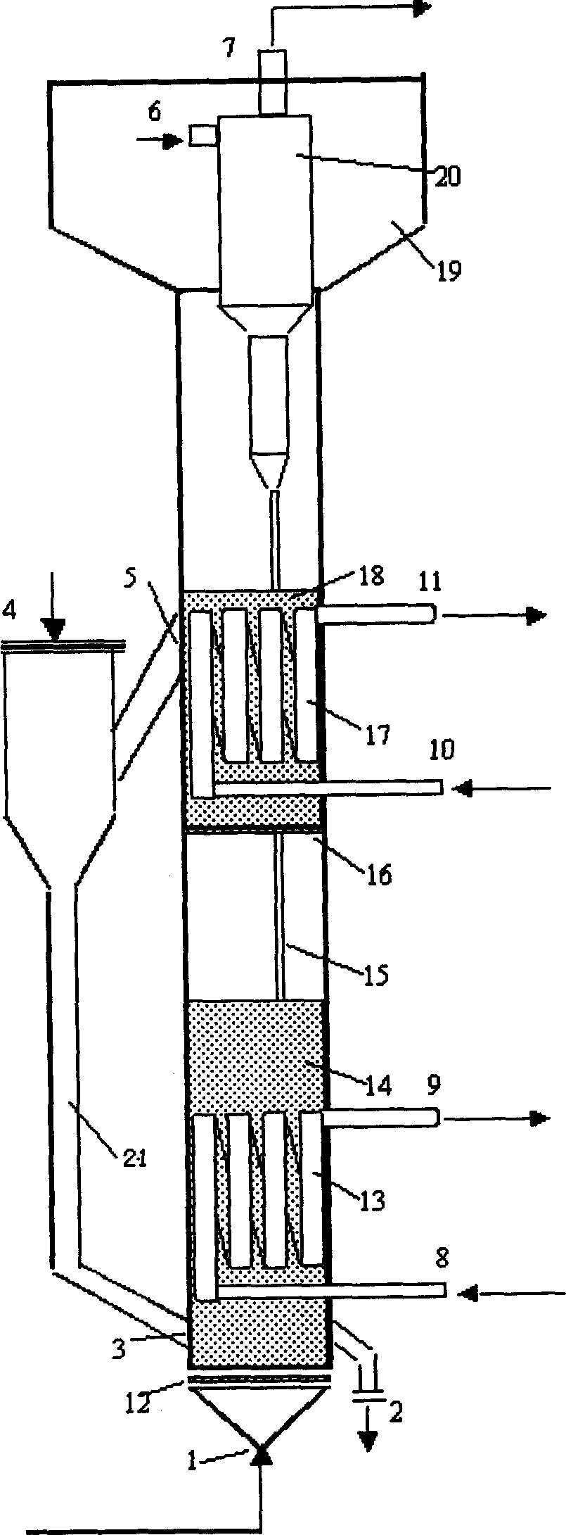
[0050] The processing method of preparing aniline of the present invention is specifically as follows:
[0051] The metal-loaded catalyst with an average particle diameter of 45-300 microns enters the reactor from the catalyst inlet 4 . In order to make the catalyst fully enter the reactor, nitrogen or air is fed through the gas distributor 12 through the gas distributor 12 at the gas raw material inlet 1 at the bottom of the reactor when adding the catalyst. Under the loosening of nitrogen or air with a small gas flow, the catalyst particles enter the reactor from the catalyst inlet 4 and mainly stay in the first catalyst dense phase zone 14 . After loading the catalyst into the reactor, pass inert gas to replace the gas in the reactor to an oxygen-free state. During this period, the temperature is gradually raised to 200-300°C, and then hydrogen gas is switched in for catalyst reduction. During the reduction, the gas velocity in the reactor is controlled between 0.05-0.6m / ...
Embodiment 1
[0057] in such as figure 1 The reaction is carried out in the two-stage fluidized bed device shown for the preparation of aniline by gas-phase hydrogenation of nitrobenzene. The feed is hydrogen and nitrobenzene, and the molar ratio is 20:1; the operating pressure (absolute pressure) is 0.25MPa; the temperature of the first catalyst dense-phase zone is 240°C, and the temperature of the second catalyst dense-phase zone is 270°C; Weight airspeed of 0.26 hours -1 , the actual gas velocity in the dense phase zone of the first catalyst is 0.45m / s. The conversion rate of nitrobenzene is 99.9993%, and the selectivity is 99.90%.
Embodiment 2
[0059] in such as figure 1 The reaction is carried out in the two-stage fluidized bed device shown for the preparation of aniline by gas-phase hydrogenation of nitrobenzene. The feed is hydrogen and nitrobenzene, and the molar ratio is 15:1; the operating pressure (absolute pressure) is 0.4MPa; the temperature of the first catalyst dense-phase zone is 240°C, and the temperature of the second catalyst dense-phase zone is 285°C; Weight airspeed of 0.4 hours -1 , the actual gas velocity in the dense phase zone of the first catalyst is 0.45m / s. The conversion rate of nitrobenzene is 99.999%, and the selectivity is 99.87%.
PUM
 Abstract
Description
Claims
Application Information