Method of crosscutting a moving web

a technology of moving webs and cross-cutting devices, applied in the direction of stock shearing machines, manufacturing tools, transportation and packaging, etc., can solve the problems of practical limitations when implemented, and achieve the effect of low required acceleration torque of the knife cylinder

Inactive Publication Date: 2005-04-19
MANROLANAD AG
View PDF8 Cites 4 Cited by
  • Summary
  • Abstract
  • Description
  • Claims
  • Application Information

AI Technical Summary

Benefits of technology

[0005]It is an object of the invention to provide a cross-cutting method in which the required acceleration torque of the knife cylinder is low.
[0007]In order to achieve a low acceleration torque of the knife cylinder with high speed changes, a low moment of inertia is striven for. This is advantageously achieved by using a knife cylinder with a small diameter, so that the circumference of the knife cylinder is small in comparison with the cut length. Thus, the circumference over which the knife cylinder can be accelerated for the subsequent cut is correspondingly reduced. However, by reversing the travel direction of the knife cylinder following the first cut, the circumferential areas over which a speed change may occur are lengthened, being configured so as to overlap. Overlapping the areas over which a speed change in the cylinder may occur when cut lengths are greater than the circumference of the knife cylinder has the advantage that the maximum driven moment of the motor needed to change the speed decreases. This occurs because the braking and acceleration travel based on the circumference of the knife cylinder may be increased up to twice the circumferential value, because of the overlap.

Problems solved by technology

Consequently, this presents practical limitations when implemented.

Method used


Image

  • Method of crosscutting a moving web
  • Method of crosscutting a moving web
  • Method of crosscutting a moving web

Examples


Embodiment Construction

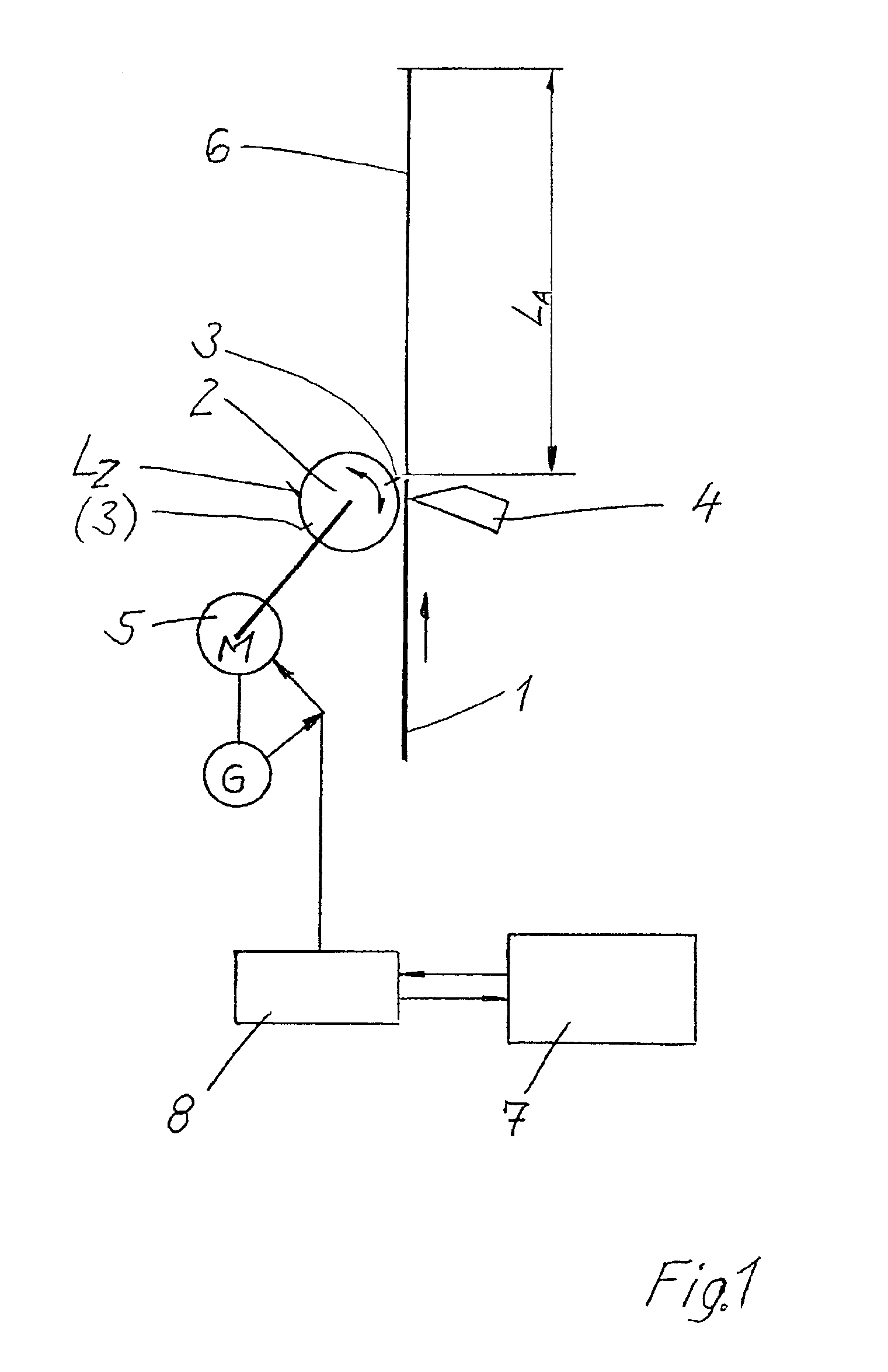
[0012]The apparatus for cross-cutting a web 1, shown in FIG. 1, includes a knife cylinder 2 fitted with at least one cutting knife 3 which during the rotation of the knife cylinder 2 rotates about its axis of rotation, wherein the axis of rotation is parallel to the cutting line.

[0013]The cutting knife 3 cooperates with an opposing knife 4 which is arranged in a fixed position. While the opposing knife 4 may rotate about an axis, it may also be designed as a cutting bar. Such a cutting bar may, for example, be housed in a folding cylinder, for example as a folding-blade cylinder of a folder. The cutting knife 3 and the opposing knife 4 can be arranged with an angular offset in relation to the cutting line to be made, in order to make a shearing cut.

[0014]It is also possible for a plurality of cutting knives to be arranged distributed uniformly on the circumference of the knife cylinder 2. For example, a second cutting knife (3) has been indicated on cylinder 2 in FIG. 1 by thinner l...


PUM

PropertyMeasurementUnit
cut lengthaaaaaaaaaa
speedaaaaaaaaaa
circumferential speedaaaaaaaaaa

Abstract

A method of cross-cutting a moving web uses a cutting knife operably mounted on a knife cylinder having a circumferential distance LZ where LZ is smaller than a cut length, LA. The knife cylinder for revolving in a first and a second opposite direction is powered by a drive motor in either direction. The method includes revolving the knife cylinder in a first direction, cutting the web with the cutting knife, and completing a first cut. The knife cylinder is then reversed to retard progress in the first direction and then accelerated to the speed of the moving web until starting the second cut.

Description

BACKGROUND OF THE INVENTION[0001]1. Field of the Invention[0002]The invention relates to a device for and a method of cross-cutting a moving web using a knife cylinder having at least one cutting knife which rotates about an axis parallel to the cutting line.[0003]2. Description of the Related Art[0004]U.S. Pat. No. 6,360,640 discloses a method of cross-cutting a web using a knife cylinder. In order to vary the length of the cut products, i.e. vary the cut length, the knife cylinder is driven at a circumferential speed that differs from the web speed, except during cutting. In the case of small cut lengths or when the knife cylinder has a plurality of cutting knives distributed uniformly over the circumference, the speed change has to be completed during a small amount of circumferential travel. This requires high accelerations and powerful up-shifting, i.e. acceleration torque, of the drive motor. Consequently, this presents practical limitations when implemented.SUMMARY OF THE INV...

Claims


Application Information

Patent Timeline
Patent Type & Authority Patents(United States)
IPC IPC(8): B26D5/20B65H35/08B65H35/04
CPCB26D5/20B65H35/08B65H2513/41B65H2513/212Y10T83/4847Y10T83/0519Y10T83/483Y10T83/4775B65H2513/23
Inventor KERSCH, ROBERTZELLER, WOLFGANG
Owner MANROLANAD AG
Why Eureka
Try Eureka