Portable irrigation device and method of use

a technology of irrigation device and watering device, which is applied in the direction of self-acting watering device, watering device, root feeder, etc., can solve the problems of time-consuming and waste, evaporation and runoff of standing water, and the use of garden hose to water, so as to reduce water waste and slow the effect of watering plants and reducing water was

Active Publication Date: 2015-09-22
MCLARTY HARVEY WAYNE
View PDF22 Cites 11 Cited by
  • Summary
  • Abstract
  • Description
  • Claims
  • Application Information

AI Technical Summary

Benefits of technology

[0024]It is an object of the present invention to overcome the above described drawbacks associated with current devices. To achieve these and other advantages and in accordance with the purpose of the invention, as embodied and broadly described, the present disclosure describes a portable irrigation device that provides for slow, efficient watering of plants and decreases water waste.
[0025]By utilizing a pressure-regulated, controlled watering method that targets water to problematic areas, the disclosed device can help plants recover from heat stress and drought. The device generally comprises an adapter configured to be connected to a water source; a pressure regulation device connected to said adapter; segments of fluid supply tubing in fluid communication with said pressure regulation device and configured to form two approximately concentric circles, wherein said two circles form an outer circle and an inner circle and wherein said outer circle is in fluid communication with said inner circle via one or more radial segments of fluid supply tubing connecting said outer circle to said inner circle; and a plurality of emitter elements disposed along said segments of fluid supply tubing at predetermined intervals.
[0026]The fluid supply tubing is made out of a flexible material, such as plastic. Segments of the tubing are joined together and arranged as at least two approximately concentric circles connected to one another by one or more radial segments of tubing. The segments of fluid supply tubing are connected in such a way that all the segments are in fluid communication with one another. This configuration provides many advantages over current irrigation devices.

Problems solved by technology

Using a garden hose to water plants, however, can be very time consuming and wasteful.
The water saturates a small area around a plant at a rate that is too high to allow the soil and plant roots time to effectively absorb the water, resulting in evaporation and runoff of the standing water.
However, because they are made of a flexible, lightweight tubing, soaker hoses have a tendency to twist and kink.
As a result, soaker hoses essentially become fixed in one place and cannot be easily moved or repositioned.
Another problem with soaker hoses occurs because the water source supplying the soaker hose is typically located two to three feet above the ground.
This configuration, combined with the high water velocity and pressure at the water source, results in significantly over-watering the area closest to the water source and under-watering the area farthest from the water source.
While manual, hose-fed sprinkler heads are inexpensive, such sprinklers must be manually moved throughout the lawn and are very time consuming to operate.
Automatic systems, however, are extremely expensive and are subject to high maintenance costs due to freezing damage, construction interference, damage during plant cultivation, rodent vandalism and damage to above ground sprinkler heads via lawn mowing equipment.
Many drawbacks of automatic and manual sprinkler systems are caused by the water delivery method used by these systems.
Sprinkler heads deliver water to the general area of a plant, rather than specifically to the root system of the plant, and as a result, these devices require much more water and time to deliver water in sufficient quantities.
Additionally, especially in hot, dry climates, water from sprinkler heads is highly susceptible to evaporation because water evaporates from droplets sprayed through the air before reaching the soil.
Plus, sloped areas of lawns are prone to discoloration because water from sprinklers runs off slopes before it has had time to be absorbed into the soil.
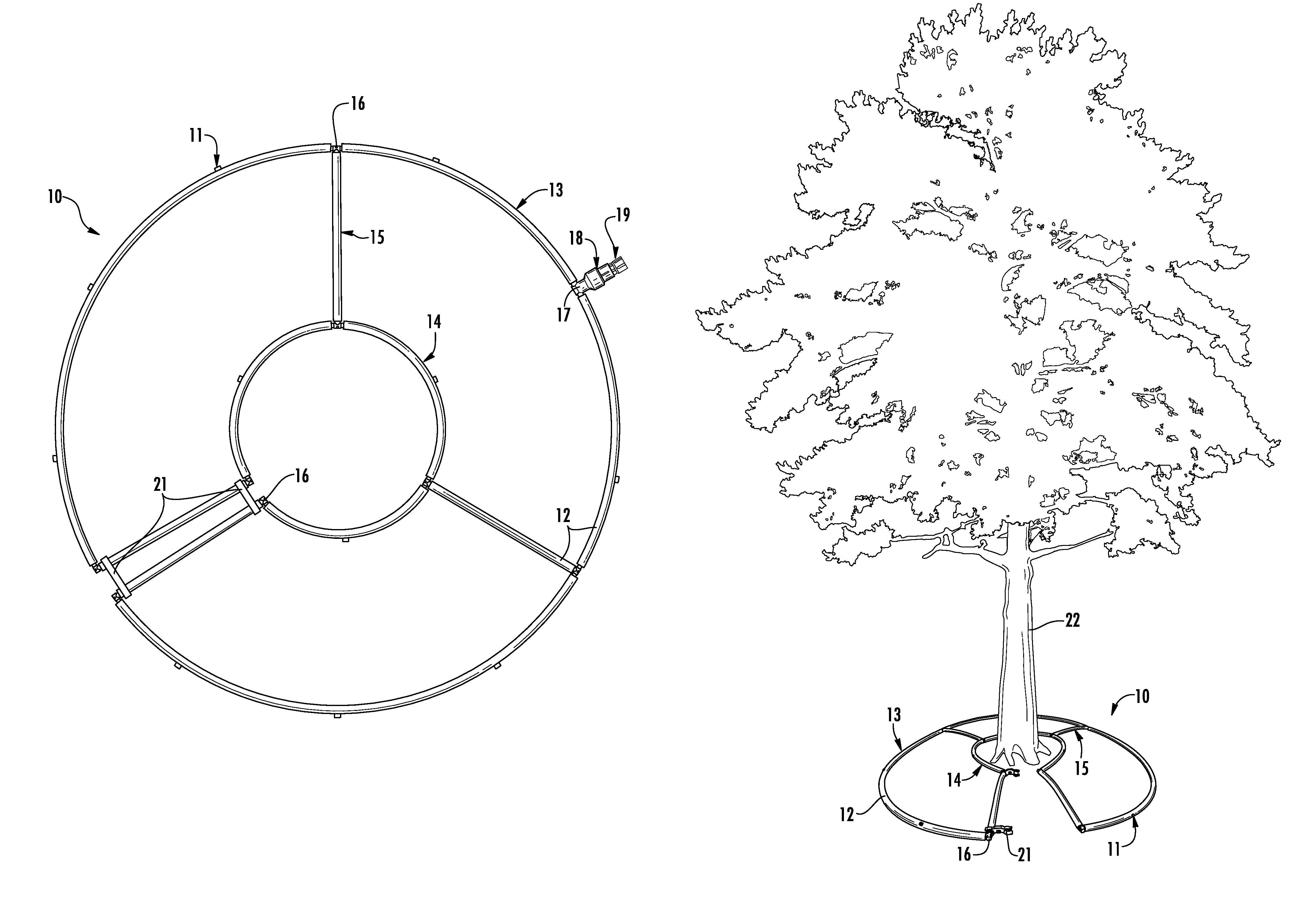
Traditional lawn and turf irrigation systems, such as sprinkler systems, that are designed primarily for delivering irrigation water over the ground surface to irrigate grass and other shallow-rooted plants have generally proven to be inadequate for proper water delivery to deep-rooted plants such as trees and large shrubs.
This type of development leaves a tree at high risk of winter injury, summer heat stress, and wind damage.
On the other hand, over-watering, which often results from using a garden hose or a soaker hose left running near the base of a tree for a long period of time, is just as harmful as inadequate watering.
Excess moisture, however, pushes oxygen from the soil and a lack of oxygen harms and can eventually kill tree roots.
Unfortunately, there are many problems with this method for watering deep subsurface plant roots.
Such watering devices and systems can be very expensive and installation is typically difficult and time consuming.
Not surprisingly, in the process of installing deep-root watering systems, users often inadvertently damage underground lines or pipes.
Also, as plant roots enlarge, they may cause harm to these underground watering devices.
Furthermore, deep-root watering with a porous device thrust into the soil is not as good for trees and other deep-rooted plants as surface applications.
Applying water below the surface misses the active roots and allows water to drain away from the roots, wasting valuable water resources.
While drip irrigation conserves water by applying water directly to the soil, thereby decreasing water waste from drift, evaporation or runoff, design problems in current drip irrigation systems present several problems.
Similar to some of the problems experienced with soaker hoses, the long lengths of drip irrigation lines, such as those made from plastic tubing, have a tendency to kink, which shuts off the flow of water to the tubing downstream from the kink.
As a result, the tubing essentially becomes fixed in one place and cannot be easily moved or repositioned.
This immobility of current drip irrigation systems causes many problems.
For example, tubing left out in the sun has a shortened usable life because the ultraviolet rays of the sun cause the tubing to become brittle and crack or break.
Also, oftentimes after installing a new drip irrigation system, a user finds that certain plants or segments of the lawn or garden are being under-watered whereas other areas are being over-watered.
However, due to the immobility of current systems, it is difficult and time-consuming to reposition or relocate the tubing to fix the uneven watering problems.
Another problem with drip irrigation systems is its unsightly appearance when left uncovered on the ground surface.
As a result, the tubing is often buried or covered by mulch or plant foliage, making it even more immobile and making it difficult to monitor the effectiveness of the system.
Buried or covered tubing is susceptible to blocked or clogged emitters, root intrusion, and harm from wayward lawn mowers, other lawn tools or rodents.
Uncovered tubing, on the other hand, becomes easy prey for pets, kids, and even vandalism in public locations.
Additionally, users face many problems when trying to use drip irrigation lines to water large plants such as trees.
Not only is it unfeasible to use drip irrigation lines for watering trees for the reasons listed above, but also, drip irrigation lines typically do not provide a sufficient supply of water to the entire root area of large trees.
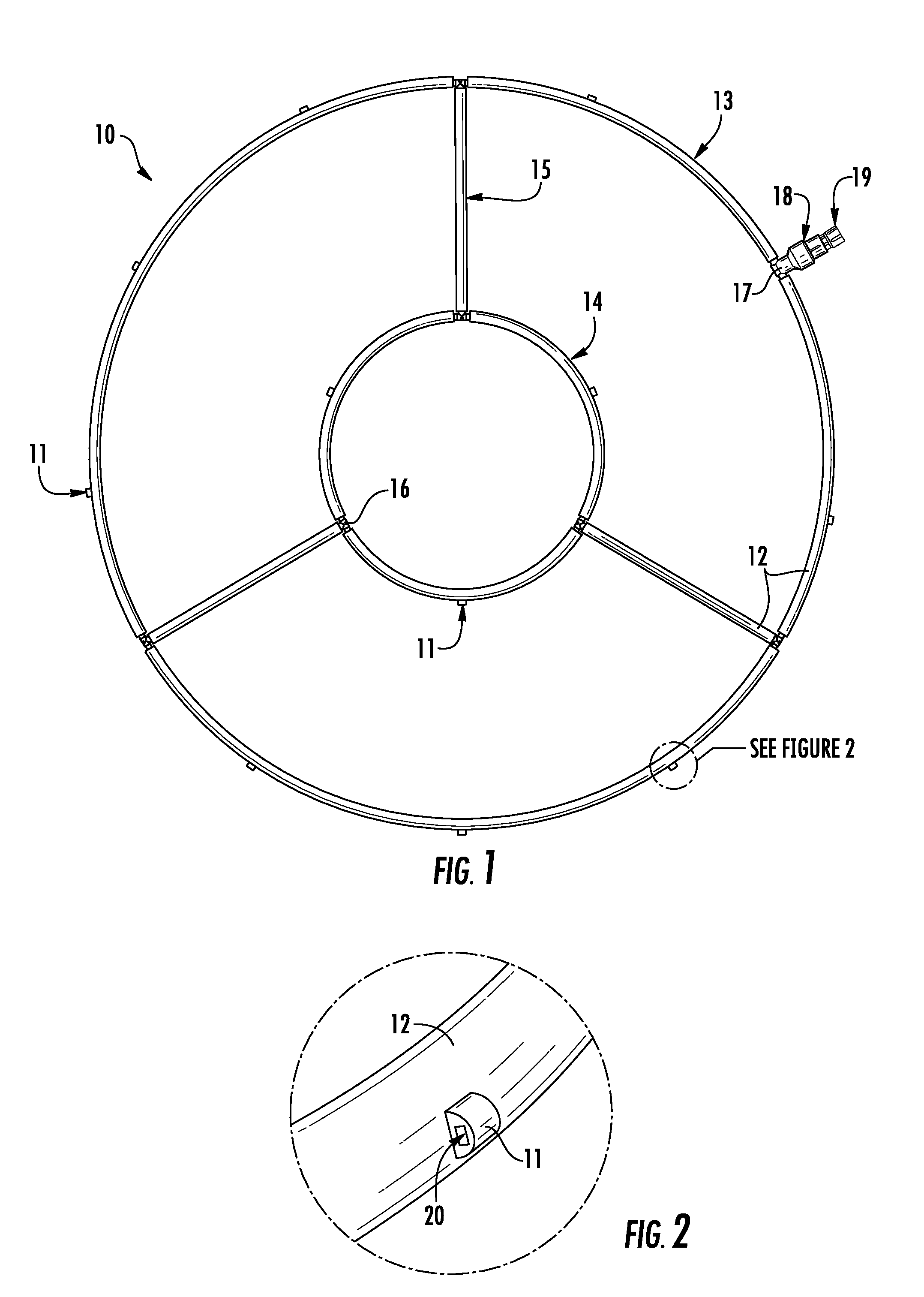
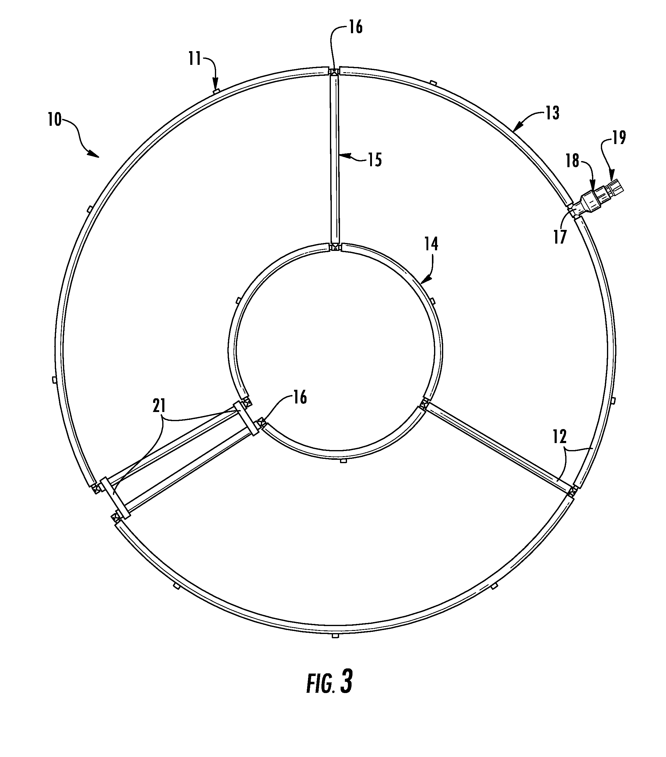
Further, a device is needed that delivers water directly to the root zone of plants in a manner that decreases the likelihood that water will be wasted due to evaporation, wind and runoff.

Method used


Image

  • Portable irrigation device and method of use
  • Portable irrigation device and method of use
  • Portable irrigation device and method of use

Examples


Embodiment Construction

[0045]Referring now to FIGS. 1-7, exemplary embodiments of a portable irrigation device 10 and methods of use in accordance with the present disclosure are illustrated.

[0046]Turning to FIG. 1, a portable irrigation device 10 according to the present disclosure is illustrated and generally includes an adapter 19 configured to be connected to a water source 23; a pressure regulation device 18 connected to said adapter 19; segments of fluid supply tubing 12 configured to be in fluid communication with said pressure regulation device 18, said tubing 12 being configured to form two approximately concentric circles 13&14, wherein said two circles form an outer circle 13 and an inner circle 14 and wherein said outer circle 13 is configured to be in fluid communication with said inner circle 14 via one or more radial segments 15 of fluid supply tubing 12 connecting said outer circle 13 to said inner circle 14; and a plurality of emitter elements 11 disposed along said segments of fluid supp...


PUM


Abstract

A portable irrigation device and a method of use are disclosed herein. The disclosed irrigation device generally comprises an adapter configured to be connected to a water source; a pressure regulation device connected to said adapter; segments of fluid supply tubing in fluid communication with said pressure regulation device and configured to form two approximately concentric circles, wherein said two circles form an outer circle and an inner circle, and wherein said outer circle is in fluid communication with said inner circle via one or more radial segments of fluid supply tubing connecting said outer circle to said inner circle; and a plurality of emitter elements disposed along said segments of fluid supply tubing at predetermined intervals. The disclosed irrigation device may be utilized to water any plant in need of targeted irrigation, including shallow-rooted plants such as flowers and dry areas of grass in lawns, as well as deep-rooted plants such as shrubs and trees.

Description

CROSS-REFERENCE TO RELATED APPLICATIONS[0001]This application is related to and claims priority from earlier filed U.S. Provisional Patent Application No. 61 / 562,100, filed Nov. 21, 2011.BACKGROUND OF THE INVENTION[0002]1. Field of the Invention[0003]The present invention relates generally to an irrigation device and method of use. More specifically, the present invention relates to a portable irrigation device and method of use that provides for slow, efficient watering of plants and decreases water waste.[0004]2. Description of the Prior Art[0005]As water increasingly becomes a scarce resource and as many cities are forced to impose water restrictions due to drought conditions, water management and conservation have become even greater concerns in lawn care programs. Currently, many different devices are available for irrigating lawns, trees, shrubs, flower beds and various other plants. Design problems in current irrigation devices, however, present several disadvantages that are...

Claims


Application Information

Patent Timeline
Patent Type & Authority Patents(United States)
IPC IPC(8): A01G25/02B05B15/06B05B1/30B05B1/14A01G27/02A01G29/00B05B1/20
CPCB05B1/3006A01G25/02A01G25/023A01G27/02A01G29/00B05B1/14B05B1/20B05B1/202B05B1/207B05B15/061B05B15/063B05B15/065B05B15/069B05B15/625B05B15/62B05B15/65B05B15/658
Inventor MCLARTY, HARVEY WAYNE
Owner MCLARTY HARVEY WAYNE
Why Eureka
Try Eureka