Toilets with improved trapways

a technology of siphon and trapway, which is applied in water closets, water installations, water closets, etc., can solve the problems of reducing the efficiency of cleaning with that little water, affecting the cleaning effect, and requiring consumers to flush multiple times, so as to improve the design of the trapway, improve the effect of the siphon and the rapid and consistent evacuation of the bowl contents

Active Publication Date: 2015-04-14
KOHLER CO
View PDF30 Cites 2 Cited by
  • Summary
  • Abstract
  • Description
  • Claims
  • Application Information

AI Technical Summary

Benefits of technology

[0013]These changes in the major and minor dimensions “focus” the flow of water through the trapway at the heel. This heel geometry facilitates the formation of a siphon in the trapway during a flushing action of the toilet, and importantly does so in a way that is effective notwithstanding a wide variation of waste that might initially be in the bowl.
[0017]The present invention provides a toilet with an improved trapway design. It is designed so that water from the bowl quickly fills key portions of the trapway during a flush cycle. This leads to rapid creation of a siphon. Additionally, the trapway design also better maintains the siphon as the water flow rate declines at the end of the flush cycle. Hence, the trapway design provides more rapid and consistent evacuation of the bowl contents, minimizing water waste.
[0018]This trapway geometry, and in particular the geometry of the heel connecting the down leg and the out leg, permits better utilization of the water during the flush cycle (e.g. more efficient splitting of water between the rim and any jet). The elongation and pinching of the heel improves the formation of a siphon in the trapway under varied water conditions while keeping the trapway free of clogs. Thus, even with relatively low amounts of water, the trapway provides an efficient, reliable, and robust flush.

Problems solved by technology

However, primarily for water conservation reasons many jurisdictions now restrict, and consumers prefer not to use, toilets that use that much water per flush.
Achieving effective cleaning when using that little water can be difficult.
Hence, some early models of low water usage toilets had problems with cleaning effectiveness, which led to consumers flushing multiple times per visit.
Others incorporated relatively expensive devices such as pumps to provide more force to the water that was used.
One impediment to reducing the amount of water used per flush cycle more is that the process of forming the siphon in the siphon leg has in the past used a substantial amount of water.
Further complicating matters is that some purported solutions lead to clogging problems.

Method used


Image

  • Toilets with improved trapways
  • Toilets with improved trapways
  • Toilets with improved trapways

Examples


Embodiment Construction

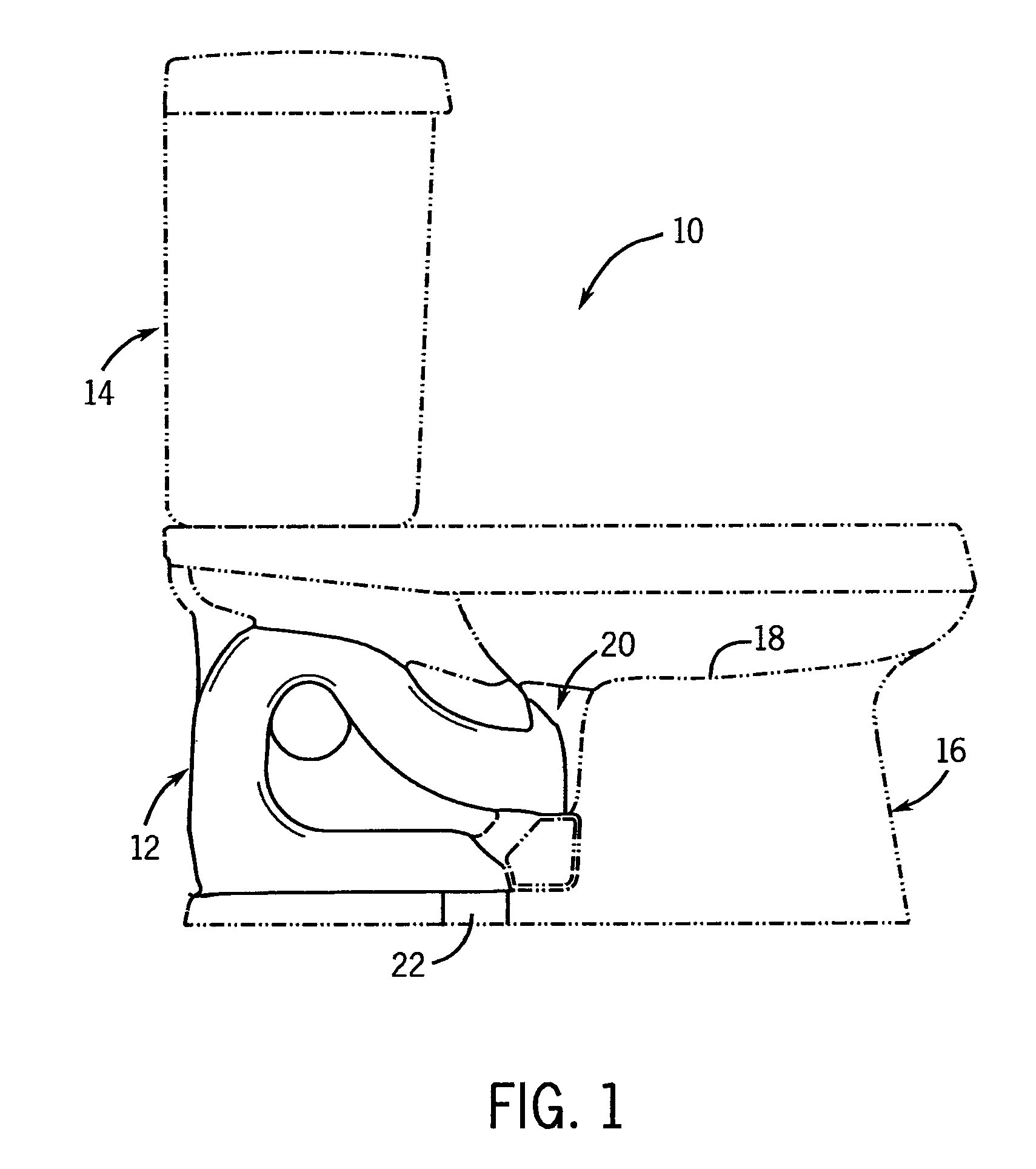
[0031]FIG. 1 illustrates a toilet 10 having a siphon passage or trapway 12 design according to the present invention. The toilet 10, apart from the specifics of the trapway 12, can be any suitable toilet, with the toilet of FIG. 11 being just one possible example.

[0032]As another example, FIG. 1 shows in dotted lines a two-piece type toilet having a flush tank 14 mounted to a bowl base 16. A hole (not shown) in the bottom of the flush tank 14 aligns with a hole (not shown) in the top of the bowl base 16 to allow water to pass from the flush tank and into a bowl 18, formed in the bowl base 16, during a flush cycle.

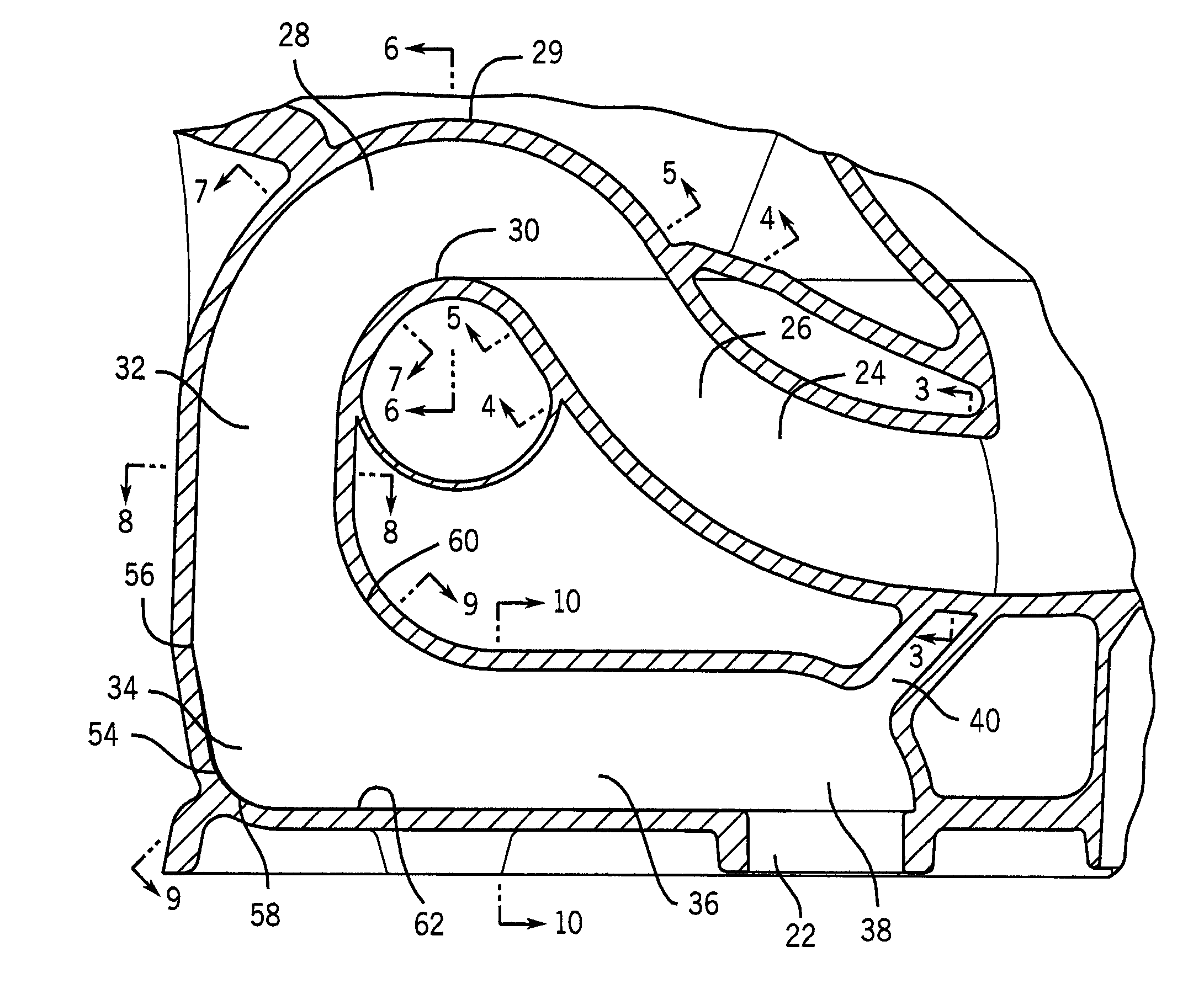
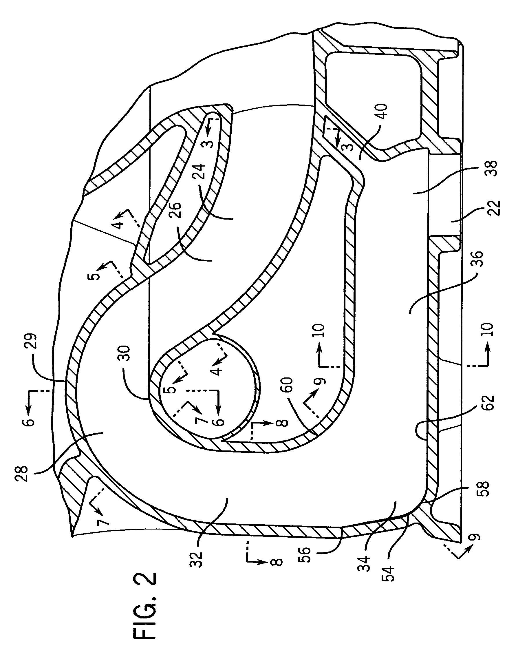
[0033]The trapway 12 extends from a bowl opening 20 in the bowl 18 along a serpentine path, and importantly has a cross-section that varies along the path (e.g. as shown in FIGS. 3-10). The trapway has an outlet opening 22 at the bottom of the bowl base 16, which mounts over the open end of a waste plumbing line (not shown). The trapway 12 thus creates a path for contents i...


PUM


Abstract

A toilet has a trapway extending between a bowl opening and a toilet outlet opening. A heel links and provides a bend between a down leg and an out leg of the trapway. The heel has a cross-sectional profile having a major dimension and a minor dimension. The major dimension increases as the down leg transitions into the heel and reduces as the heel transitions into the out leg. This heel configuration in the trapway forms a siphon during a flushing action of the toilet.

Description

CROSS-REFERENCE TO RELATED APPLICATION[0001]Not applicable.STATEMENT OF FEDERALLY SPONSORED RESEARCH OR DEVELOPMENT[0002]Not applicable.BACKGROUND OF THE INVENTION[0003]The present invention relates to toilets having siphonic outlet traps extending from their bowl. More particularly it relates to improvements in such traps to facilitate bowl cleaning with lower water usage.[0004]Conventional toilets typically have a bowl portion connected to a serpentine outlet passage. An up leg portion of the passage is normally filled with water between flush cycles to “trap” sewer gases downstream thereof, so as to thereby prevent the sewer gases from entering the building interior.[0005]Water is maintained in the bowl and the up leg part of the trapway by an arched portion of the trapway known as a “weir”. A down leg of the trapway which is downstream of the weir is a leg that is designed to develop a siphon once the flushing cycle starts, to help further evacuate the bowl. Downstream of that i...

Claims


Application Information

Patent Timeline
Patent Type & Authority Patents(United States)
IPC IPC(8): E03D11/18E03D11/08
CPCE03D11/18E03D11/08
Inventor MESUN, RANDY O.HALLORAN, DANIEL N.
Owner KOHLER CO
Why Eureka
Try Eureka