Integral support stent graft assembly

a stent and graft technology, applied in the field of stent grafts, can solve the problems of high production cost, troublesome manufacture and use of stent grafts, and fatal acute rupture of aneurysms, and achieve the effects of low production rate, high production cost, and bulky stent grafts

Active Publication Date: 2006-10-17
THE SECANT GRP
View PDF22 Cites 201 Cited by
  • Summary
  • Abstract
  • Description
  • Claims
  • Application Information

AI Technical Summary

Benefits of technology

[0028]It is advantageous to provide a region of enhanced biocompatibility positioned on the tube of the stent adjacent to the reverse fold. The region of enhanced biocompatibility faces radially outwardly and facilitates the formation of a biological seal between the stent graft and the vascular vessel.

Problems solved by technology

Such aortic aneurysms constitute a serious condition, as an acute rupture of the aneurysm is fatal unless an emergency operation is performed.
However, even when such operations are performed in time, the mortality rate is still greater than 50%.
However, the manufacture and use of stent grafts is troublesome and expensive for several reasons.
Hand suturing is done by skilled workers, and each piece takes a relatively long time to complete, resulting in low production rates and high production costs.
Furthermore, sutures can become untied during the operation or after the stent graft is implanted.
The consequences of a failure after an operation could, of course, be fatal.
The free graft end could also fold and partially block the artery, again with potentially fatal results.
This is undesirable because it limits the minimum size of the catheter usable to implant the stent graft.
The stent graft must fit within and advance along the bore of the catheter during the operation, and the bulkier the stent graft the larger a catheter is required, thereby limiting the size of artery which can be treated by the implantation of a stent graft.
Sutures also tend to snag on the walls or tip of the catheter, thus, making it difficult to smoothly advance the stent graft along the bore or readily release it from the catheter, potentially complicating the operation.
Finally, because sutures are expensive and time consuming to use, tend to increase the bulk of the stent graft and tend to snag the walls of the catheter, they are used sparingly to attach the stent and hooks to the graft.
Fewer attachment points means greater potential for failure at some point during or after the operation.
Stent grafts positioned within the catheter tend to stiffen it and reduce its ability to bend and easily traverse the artery for accurate positioning of the tip.
The longer and more bulky the stent grafts are the more they stiffen the catheter, thereby increasing any disadvantage.
Furthermore, stent grafts generally require a sheath within the catheter, thereby further increasing bulk and thus stiffness of the catheter.
Too small a stent diameter will cause one or more folds to occur in the artery, leading to an incomplete seal and leakage into the aneurysm.
Too large a stent diameter will result in a fold in the graft, also causing a leak as well as an obstruction within the artery that impedes the flow of blood and which may become a point where clots form and break off to later lodge in the artery and form an embolism.
If the length of a branch is insufficient, then the branch may not bridge the diseased region of the artery, placing additional stress on an already weakened artery wall.
If the lengths are too great, then the branches may kink and impede blood flow.
The impracticality of both solutions leads to significant expense in the treatment of vascular disorders.

Method used


Image

  • Integral support stent graft assembly
  • Integral support stent graft assembly
  • Integral support stent graft assembly

Examples


embodiment 150

[0062]FIG. 9 illustrates the use of a integral support stent graft assembly embodiment 150 according to the invention to treat a descending aortic aneurysm 152. As shown in detail in FIG. 10, stent graft assembly 150 comprises a base module 154 having a main central space 156 and four branch central spaces 158, 160, 162 and 164 in fluid communication with the main central space. The central spaces are defined by a perimetral sidewall 166 comprising a main sidewall portion 168 and various branch sidewall portions 170, 172, 174 and 176. As described above, the central spaces are formed by attaching opposing portions of the perimetral sidewall 166 to one another along lines of attachment 178, 180 and 182, each line of attachment having a terminal point forming a respective shoulder 184, 186 and 188.

[0063]As shown in FIG. 9, the distal end 190 of base module 154 has a stent 192 for attachment to healthy aortic tissue. The proximal end 194 is flared to receive limbs 196, 198, 200 and 202...

embodiment 260

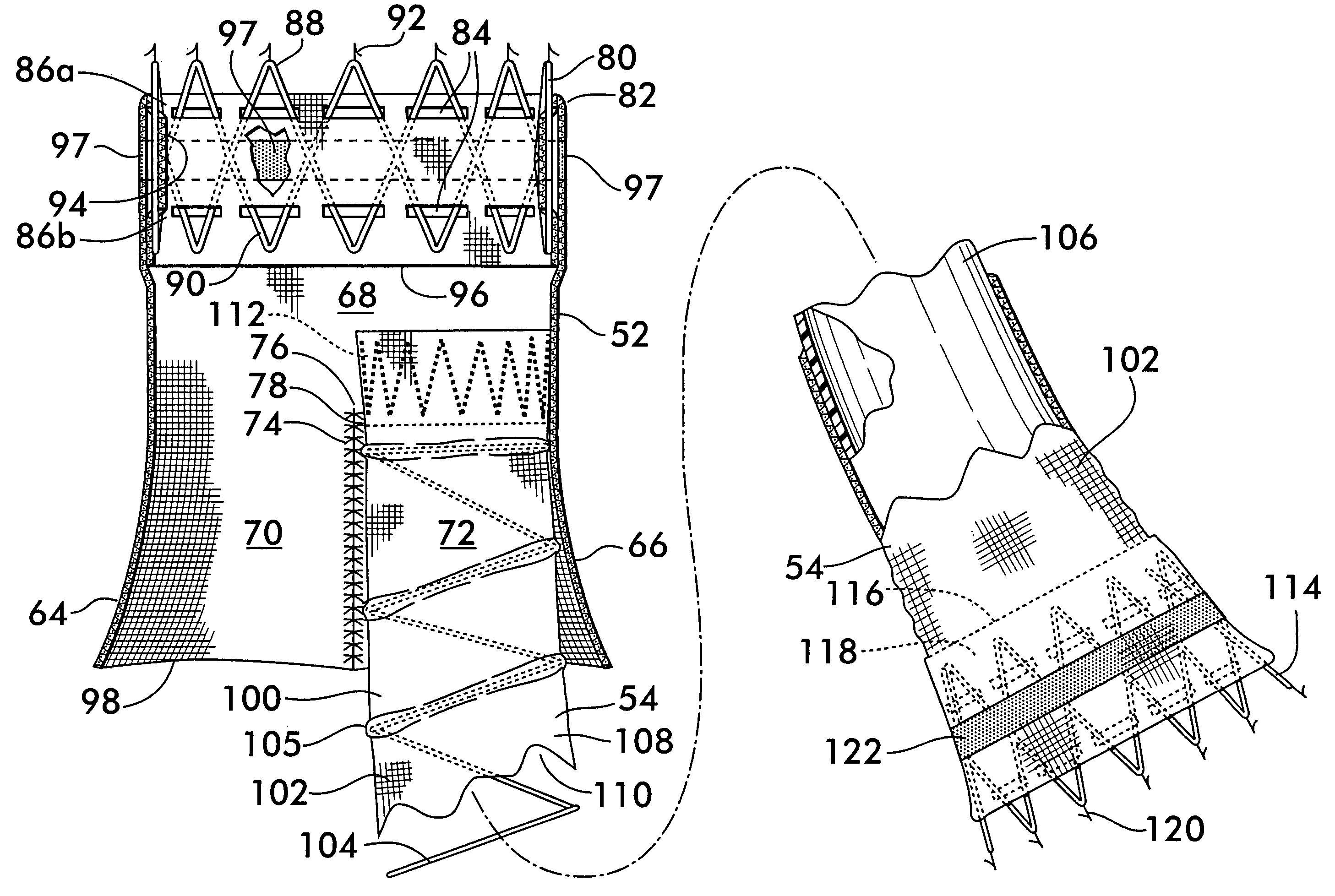
[0066]Another embodiment 260 of the integral support stent graft assembly is shown in FIG. 12. Embodiment 260 is useful to repair aneurysm 10 in abdominal artery 12 where there is no healthy tissue region between the renal arteries 14a and 14b and the aneurysm 10 to which the stent graft assembly may be attached. In stent graft assembly 260, a stent 262 attaches a base module 264 to healthy tissue above the renal arteries 14a and 14b. The base module 264 comprises a perimetral sidewall 266 and is subdivided into three compartments, 268, 270 and 272. The division is made using lines of attachment 274 and 278 joining opposing portions of the perimetral sidewall 266 together. The base module 264 is further subdivided into branch sidewall portions 280 and 282 for receiving limbs as described above.

[0067]All three compartments 268, 270 and 272 are in fluid communication with the branch sidewall portions 280 and 282, but the outermost positioned compartments 268 and 272 are also in fluid ...


PUM


Abstract

A stent graft is disclosed having a tubular graft formed from flexible filamentary members interwoven with a supporting monofilament defining radial corrugations around the graft. The ends of the graft are tapered from a smaller to a larger diameter and have stents attached thereto for engagement with a vascular vessel. The stents are attached to the graft by passing through two rows of slots cut in the graft and arranged in spaced relation to one another. The slots are positioned on a reverse fold of the graft to capture the stent. The stent graft may be modular and have limbs insertable into a base module. The base module has a main central space in communication with branch central spaces defined by a line of attachment between the branch central spaces. The terminus of the line of attachment forms a shoulder for retaining the limbs.

Description

FIELD OF THE INVENTION[0001]This invention relates to stent grafts for treatment of vascular disorders and includes stent grafts assembled from modular components.BACKGROUND OF THE INVENTION[0002]The vascular system is subject to various disorders, among the more serious being occlusive diseases and aneurysms. Occlusive diseases refer to the closing of vessels such as the iliac, carotid, biliary and coronary arteries. Aneurysms are defined as a pathologic dilation of a vessel and can affect the aortic, thoracic, renal and iliac arteries among others.[0003]Effective treatment of many occlusive diseases and aneurysms is possible through the use of an endovascular stent graft. The stent graft comprises a tubular structure (the “graft”) which effects a connection between portions of a vascular vessel. The graft is typically flexible and preferably formed of biocompatible filaments or yarns interlaced by weaving, knitting or braiding to form a tube or sleeve. The stent is positioned circ...

Claims


Application Information

Patent Timeline
Patent Type & Authority Patents(United States)
IPC IPC(8): A61F2/06A61B
CPCA61F2/07A61F2002/061A61F2002/067A61F2002/075A61F2/88A61F2/89A61F2230/0054A61F2250/0007
Inventor GREENHALGH, E. SKOTT
Owner THE SECANT GRP
Why Eureka
Try Eureka