Compact suture punch with malleable needle

a suture punch and malleable technology, applied in the field of surgical suturing, can solve the problems of insufficient jaw opening space, difficult to force the tooth through the full thickness of the tissue, and difficult to pass through the sutur

Inactive Publication Date: 2006-09-26
MORRIS JOHN K +1
View PDF99 Cites 224 Cited by
  • Summary
  • Abstract
  • Description
  • Claims
  • Application Information

AI Technical Summary

Benefits of technology

[0015]This invention overcomes deficiencies in the prior art by providing a suture punch system capable of directly passing braided suture through tissue in a simple, one-step process. The system includes three principle components: a malleable needle with braided suture attached, a handheld instrument for grasping tissue and controlling needle placement, and a trocar to supply the force required for needle formation and placement.
[0017]In contrast to existing suture punches in which the needle or shuttle undergoes only an elastic deformation during use and the functional un-constrained shape of the needle or shuttle is produced during manufacture, the needle of the disclosed device is inelastically formed to its functional shape during use, allowing the needle to traverse a nonlinear path. More particularly, when passing through the distal tip of the hand instrument, the needle is inelastically formed by a radial path within the instrument, the plane of the radius being preferably perpendicular to the tissue through which suture is being passed. The formation of this radius is facilitated by the aforementioned parallel sides of the needle cross-section which are constrained by the instrument in such a manner as to place them essentially in the plane of the tissue.
[0019]Forming of the needle along its length continues as it is passes from the distal tip of the instrument into the tissue. When the proximal end of the needle exits from the instrument, the needle is entirely radial in shape and traverses an essentially radial path through the tissue. After the proximal end of the needle exits the instrument, the needle is propelled further along its radial path by the trocar, the distal portion of the trocar being formed to a radial shape by the instrument in the same manner as the needle and the radial shapes of the needle and trocar being coplanar. Engagement of the trocar with the needle after the needle passes from the instrument may be facilitated by mating surfaces of the trocar and needle, shaped, for example, to prevent radial or lateral displacement of the needle proximal and trocar distal surfaces.

Problems solved by technology

Suture passing is problematic for the arthroscopic surgeon because the braided suture preferred by most arthroscopists cannot be pushed through a cannulated instrument.
A shortcoming of these and other such devices is the lack of room available to open the jaws sufficiently in tight spaces (a clearance issue), difficulty in forcing the tooth through the full thickness of the tissue (the tip gradually dulls and some tissue like the rotator cuff is just too thick) and fairly large diameter cannulas are required for passage.
These are cumbersome to use, often requiring skillful rotation and pushing of the device by the surgeon to accomplish the desired result.
Additionally, some concern exists with regard to the size of the hole placed in the tissue and the amount of damage requiring repair.

Method used


Image

  • Compact suture punch with malleable needle
  • Compact suture punch with malleable needle
  • Compact suture punch with malleable needle

Examples


Embodiment Construction

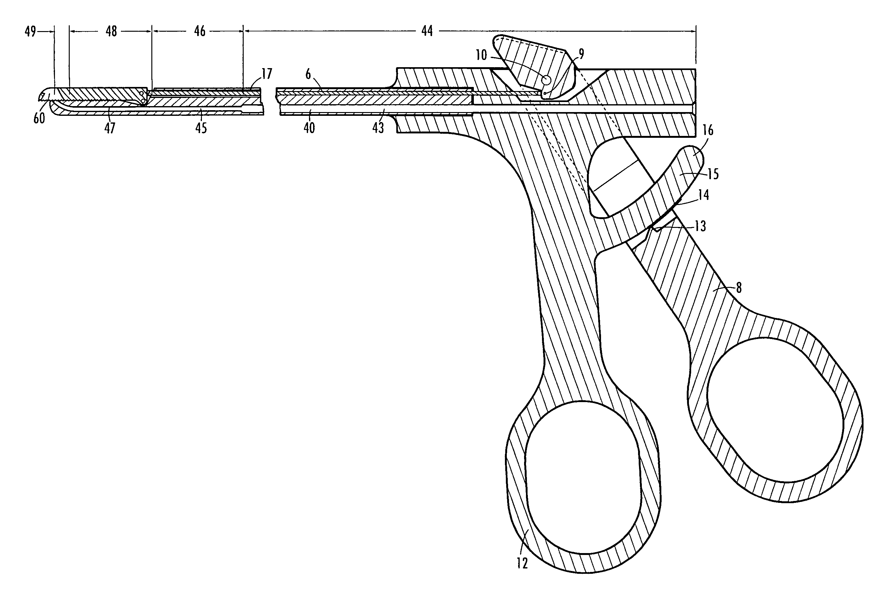
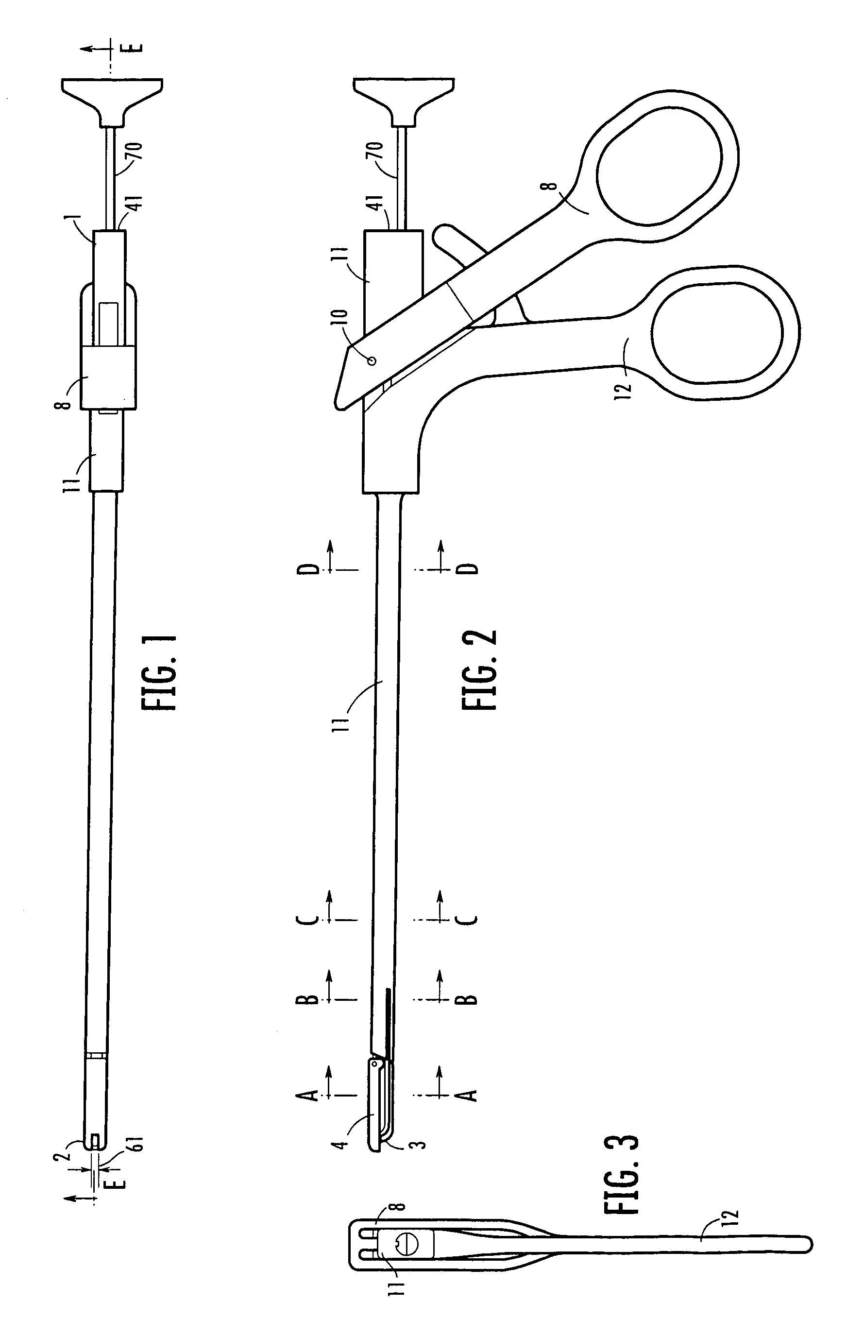
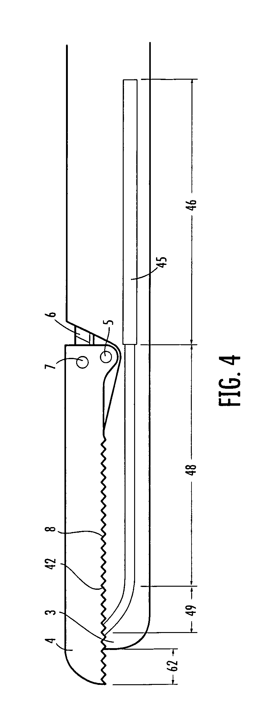
[0138]Referring to the drawings, as best seen in FIGS. 1 through 9, the instrument body 11 has a proximal end 1 and a distal end 2. The distal end further includes a fixed portion (or fixed jaw) 3 and a movable portion (or moveable jaw) 4. The movable portion 4 is rotatable about pin 5 passing through the movable portion 4 and fixed portion 3 thereby forming a hinge.

[0139]The position of movable jaw 4 is determined by positioning rod 6 which transmits an opening or closing force to movable portion 4 via hinge pin 7. The position of positioning rod 6 is determined by the position of movable handle 8, which is connected to the proximal end of positioning rod 6 through pin 9. The positioning rod 6 passes through elongated section 18 of instrument body 11 and through passage 17.

[0140]Movable handle 8 is rotatably affixed to the instrument body 11 by pin 10 so that rotating movable handle 8 counterclockwise opens movable jaw 4 and rotating movable handle 8 clockwise closes movable jaw 4 ...


PUM


Abstract

A suture punch system is capable of directly passing braided suture through tissue in a simple, one-step process. The system includes three principle components: a malleable needle with braided suture attached, a handheld instrument for grasping tissue and controlling needle placement, and a trocar to supply the force required for needle placement. Needle deformation begins at the tip of the instrument, which preferably includes a curved segment. As the distal tip of the needle pierces the tissue, it continues its radial path through the tissue. When the proximal end of the needle exits from the instrument, the needle is entirely radial in shape and traverses an essentially radial path through the tissue. Non-radial linear or non-linear segments may alternatively be used. In one embodiment, the tissue to be sutured is constrained by pressure applied through closure between an upper, moveable jaw the distal portion of the instrument which acts as a fixed jaw. The upper, movable jaw contains a shaped passageway which allows the curved needle to pass therethrough during use. Once the needle has passed entirely through the tissue it is ready for retrieval using the jaws of the punch or another instrument. Different needle designs and separate instruments are also disclosed.

Description

REFERENCE TO RELATED APPLICATION[0001]This application claims priority from U.S. Provisional Patent Application Ser. No. 60 / 310,220, filed Aug. 6, 2001; the entire content of this application is incorporated herein by reference.FIELD OF THE INVENTION[0002]This invention relates generally to surgical suturing and, in particular, to improved articles, instrumentation, and methods therefore.BACKGROUND OF THE INVENTION[0003]Suture passing is problematic for the arthroscopic surgeon because the braided suture preferred by most arthroscopists cannot be pushed through a cannulated instrument. Braided suture must be pulled into location because applying a push force causes the braid to expand in diameter, thereby wedging in the instrument.[0004]Various solutions have been devised for passing braided suture. The Caspari Suture Punch (Linvatec Corporation, Largo, Fla.) has been a very useful arthroscopic suture-passing instrument. Tissues can be approached head on, grasped and punctured with ...

Claims


Application Information

Patent Timeline
Patent Type & Authority Patents(United States)
IPC IPC(8): A61B17/62A61B17/06A61B17/04A61B17/28
CPCA61B17/0469A61B17/0482A61B17/0625A61B17/062A61B17/06066A61B2017/2926A61B2017/00946A61B2017/0496
Inventor MORRIS, JOHN K.VAN WYK, ROBERT A.
Owner MORRIS JOHN K
Why Eureka
Try Eureka