Coiled ablation catheter system

Inactive Publication Date: 2005-11-01
THE GENERAL HOSPITAL CORP
View PDF36 Cites 196 Cited by
  • Summary
  • Abstract
  • Description
  • Claims
  • Application Information

AI Technical Summary

Benefits of technology

[0009]In one embodiment, a cardiac ablation catheter system includes an elongate, flexible sheath having an internal lumen and an open distal end. An ablating element is disposed within the sheath and is selectively deployable therefrom so as to project from the sheath in a substantially coil-like shape. In an exemplary embodiment, the deployed ablating element

Problems solved by technology

Atrial fibrillation results from rapidly discharging foci and causes irregular heart beats, possibly leading to inefficient pumping of bl

Method used


Image

  • Coiled ablation catheter system
  • Coiled ablation catheter system
  • Coiled ablation catheter system

Examples


Embodiment Construction

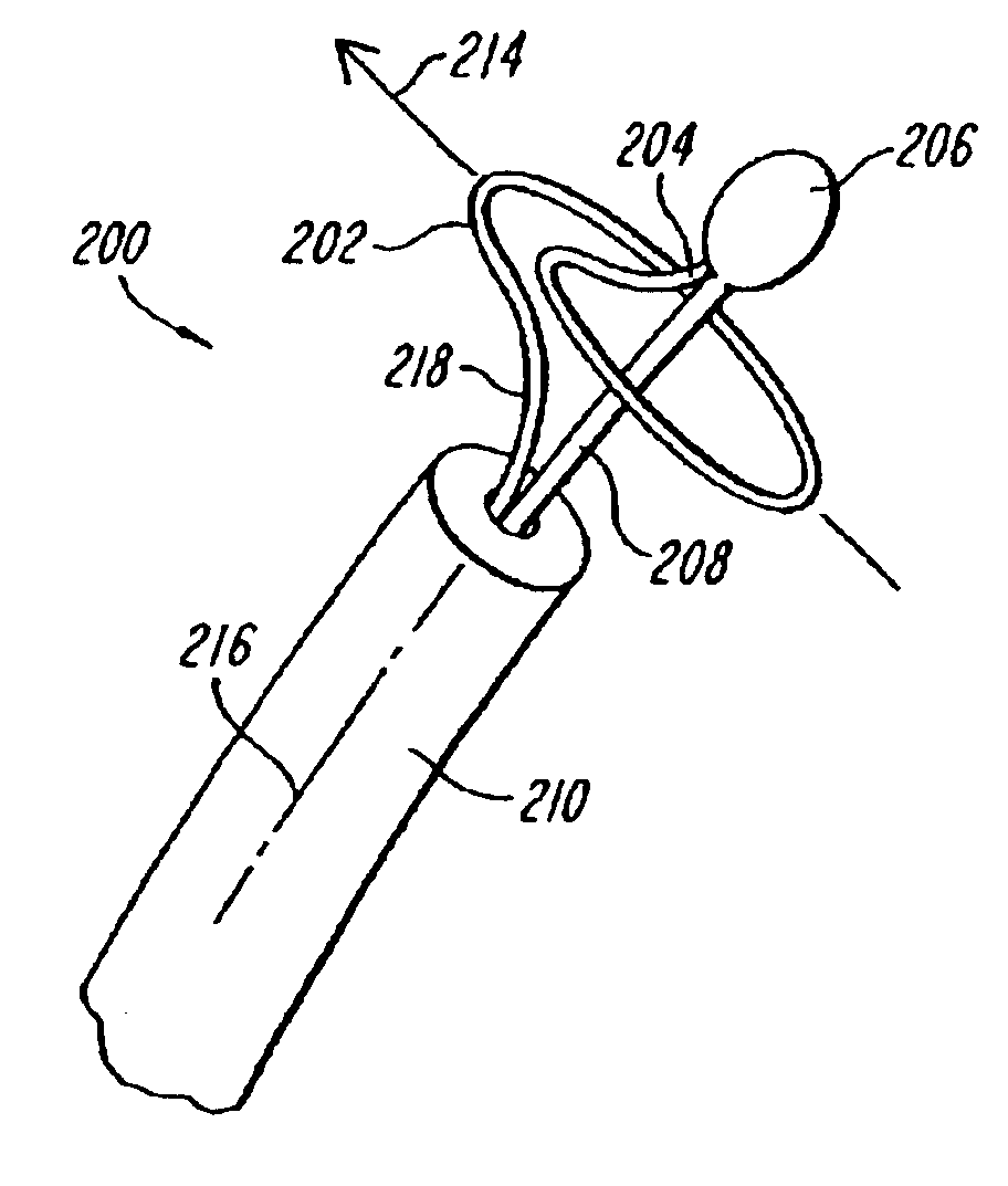
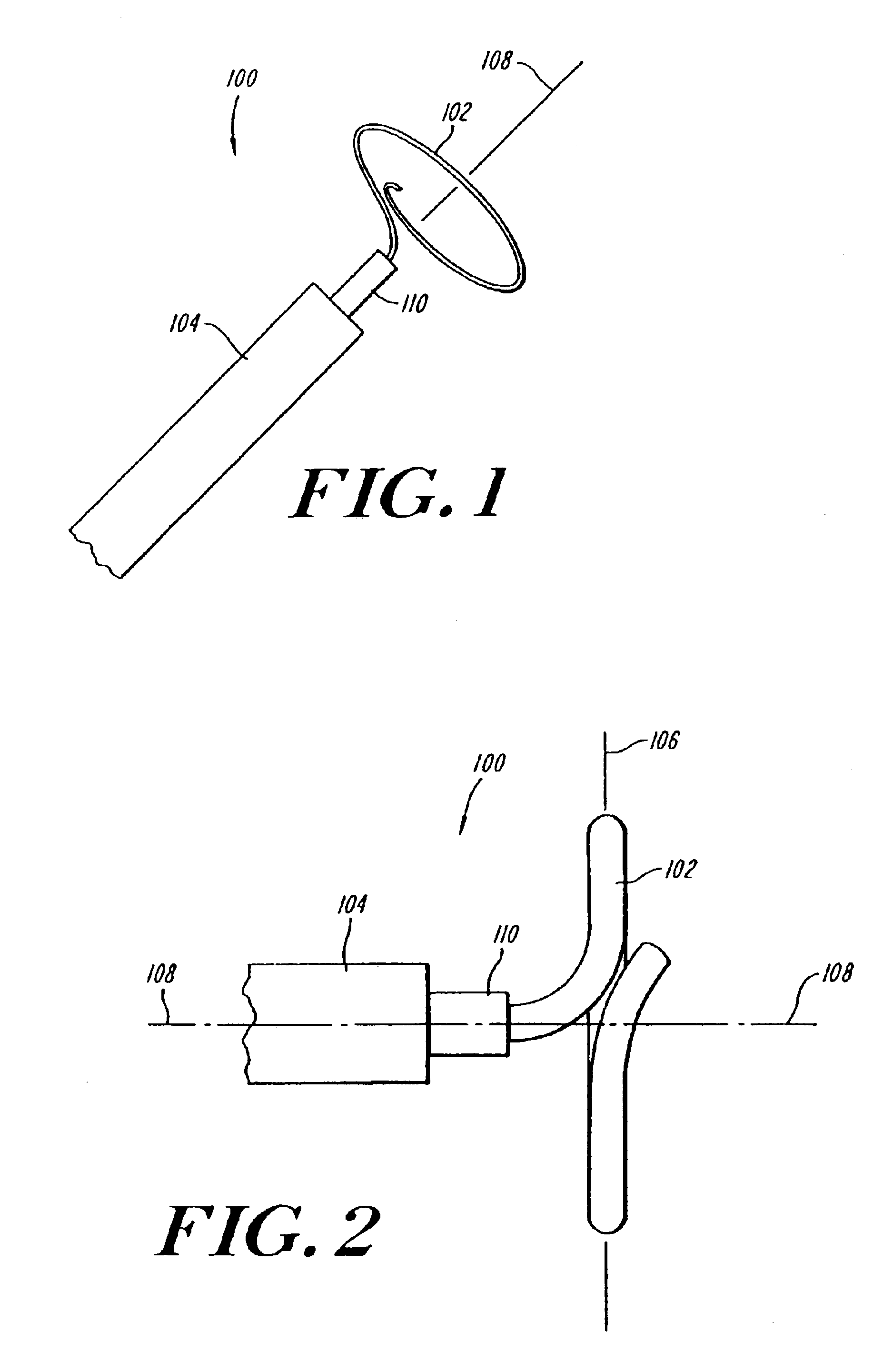
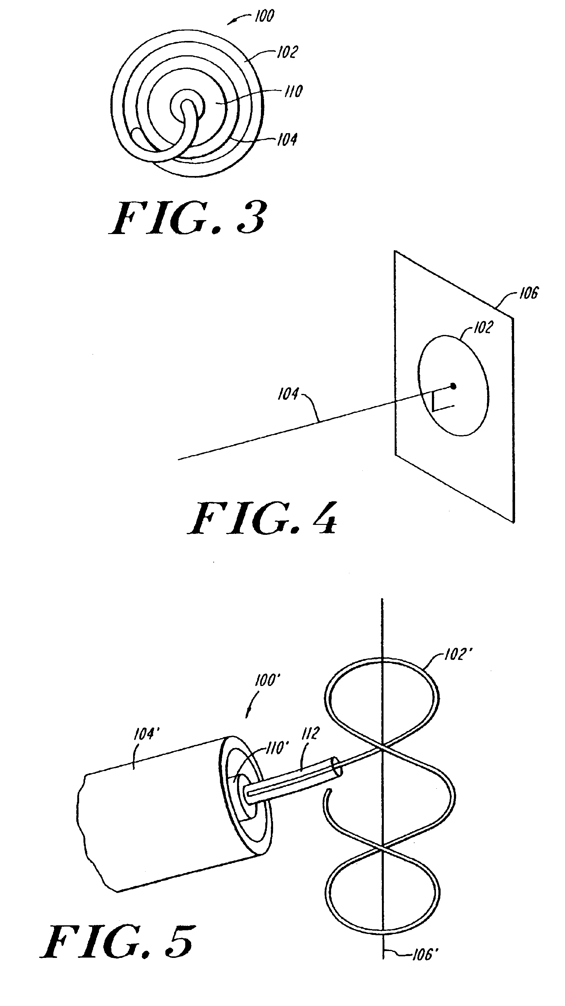
[0025]FIGS. 1-3 show an ablation catheter system 100 in accordance with the present invention having an ablation element 102 that is deployable from a flexible elongate catheter or sheath 104. The catheter sheath 104 should be semi-rigid and flexible so as to be readily steerable to a desired location in a patient=s body, such as proximate the os of a pulmonary vein. Such catheter delivery systems are well known to those of ordinary skill in the art. In general, the deployed coil-like ablation element 102 has a shape that includes one or more revolutions substantially oriented in a transverse plane 106 (FIG. 4) that is orthogonal to a longitudinal axis 108 of the sheath 104. This geometry facilitates treating tissue about a circumference of a vessel, such as a pulmonary vein. The circumferential region of ablated tissue electrically isolates tissue on opposite sides of the ablated tissue. Thus, the atria, for example, can be electrically isolated from any arrhythmia-inducing foci wi...


PUM

PropertyMeasurementUnit
Shape memory effectaaaaaaaaaa
Shapeaaaaaaaaaa
Radiusaaaaaaaaaa

Abstract

A cardiac ablation catheter includes a coil-like ablating element that is deployable from an elongate, flexible sheath. The ablating element, while in the deployed position, has a shape with at least one revolution oriented in a plane that is orthogonal to a longitudinal axis of the sheath. The catheter system is well-suited to ablate a circumferential region of tissue about a pulmonary vein or the posterior wall of the left atrium proximate the pulmonary vein os. The treated tissue region electrically isolates the atria from the pulmonary vein.

Description

CROSS-REFERENCE TO RELATED APPLICATIONS[0001]This application is a continuation of application Ser. No. 09 / 396,959 filed Sep. 15, 1999, now U.S. Pat. No. 6,607,520 titled “Coiled Ablation Catheter System,” which is hereby incorporated by reference in its entirety.STATEMENT REGARDING FEDERALLY SPONSORED RESEARCH[0002]Not Applicable.FIELD OF THE INVENTION[0003]The present invention relates generally to catheter systems, and more particularly, to catheter systems for ablating and / or isolating foci that contribute to cardiac arrhythmia.BACKGROUND OF THE INVENTION[0004]Catheters are commonly used in surgical procedures to access certain areas of a patient=s body without resorting to invasive surgical procedures. For example, catheters are widely used in the field of cardiology to conduct electrophysiological studies in which electrical potentials within the heart are mapped to determine the cause and location of arrhythmia. In many cases, certain undesired conductive pathways, known as f...

Claims


Application Information

Patent Timeline
IPC IPC(8): A61B18/14A61F2/06A61B18/02A61B18/00A61B17/00A61F2/82A61F2/88
CPCA61B18/1492A61F2/88A61B18/02A61B2017/00867A61B2017/2212A61B2017/2215A61B2017/2217A61B2018/00029A61B2018/00083A61B2018/00136A61B2018/00214A61B2018/00375A61B2018/1435A61B2018/1497A61F2002/821
Inventor KEANE, DAVID
Owner THE GENERAL HOSPITAL CORP
Why Eureka
Try Eureka