This helps you quickly interpret patents by identifying the three key elements:
Problems solved by technology
Method used
Benefits of technology
Benefits of technology
[0011]The Waterbug fulfills this requirement by generating its own power. The Waterbug is powered by the pressure of the water flowing through it. This gives the Waterbug substantial advantages over previous sprinkler control systems, because it uses a reduced amount of electrical power.
[0012]The Waterbug includes sensors that sense the amount of water that is present in the soil. When the amount of water present in the soil reaches a pre-programmed amount, the Waterbug turns off the water flowing into the sprinkler system. The Waterbug therefore reduces water waste significan
Problems solved by technology
However, the devices disclosed in U.S. Pat. No. 7,836,910 B2 do not have the versatility, or the capability, to be connected with every type of sprinkler system.
The device described in U.S. Pat. No. 7,613,546 cannot generate its own internal power.
H
Method used
Image
Click on the blue label to locate the original text in one second.
Reading with bidirectional positioning of images and text.
Examples
Example
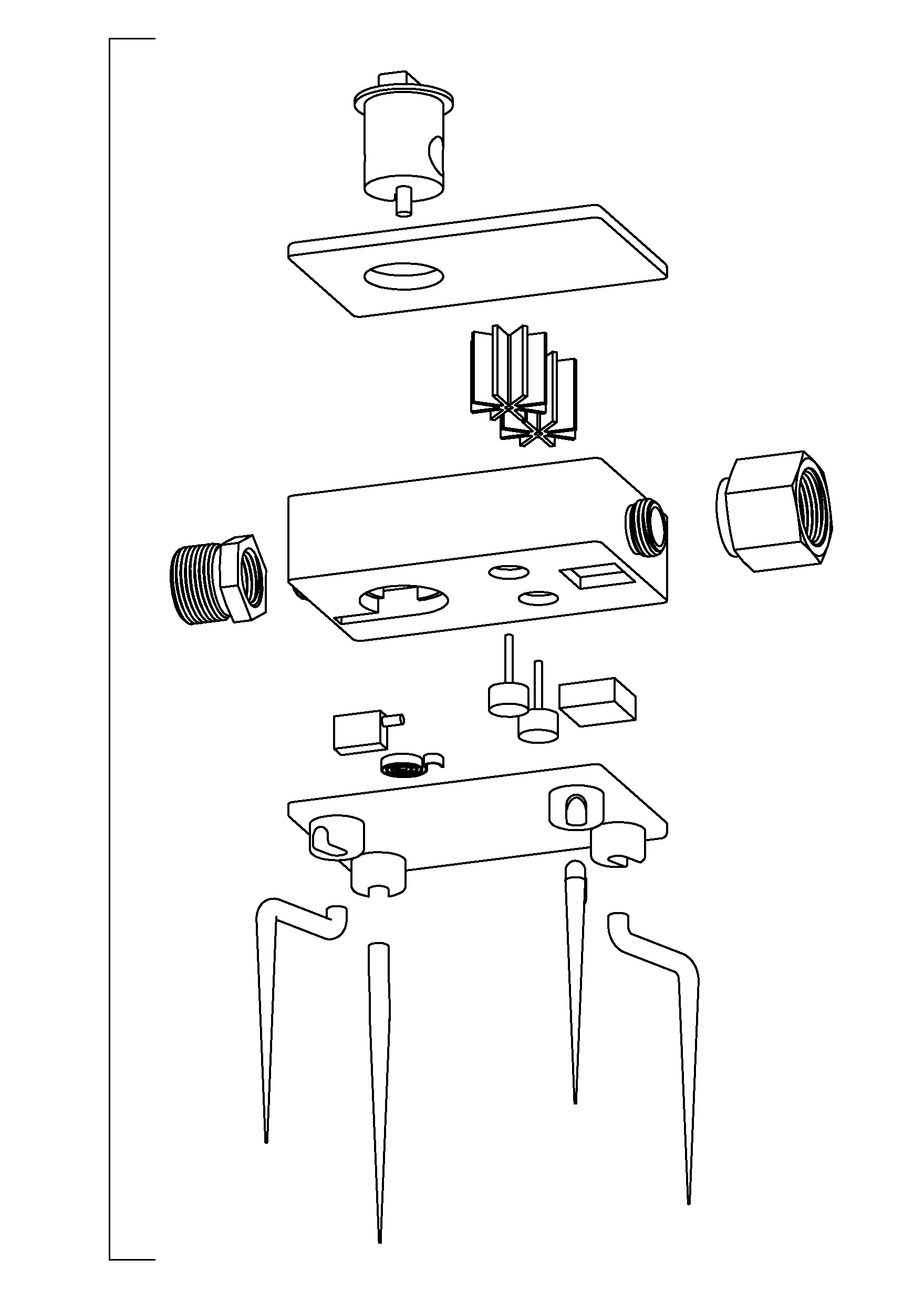
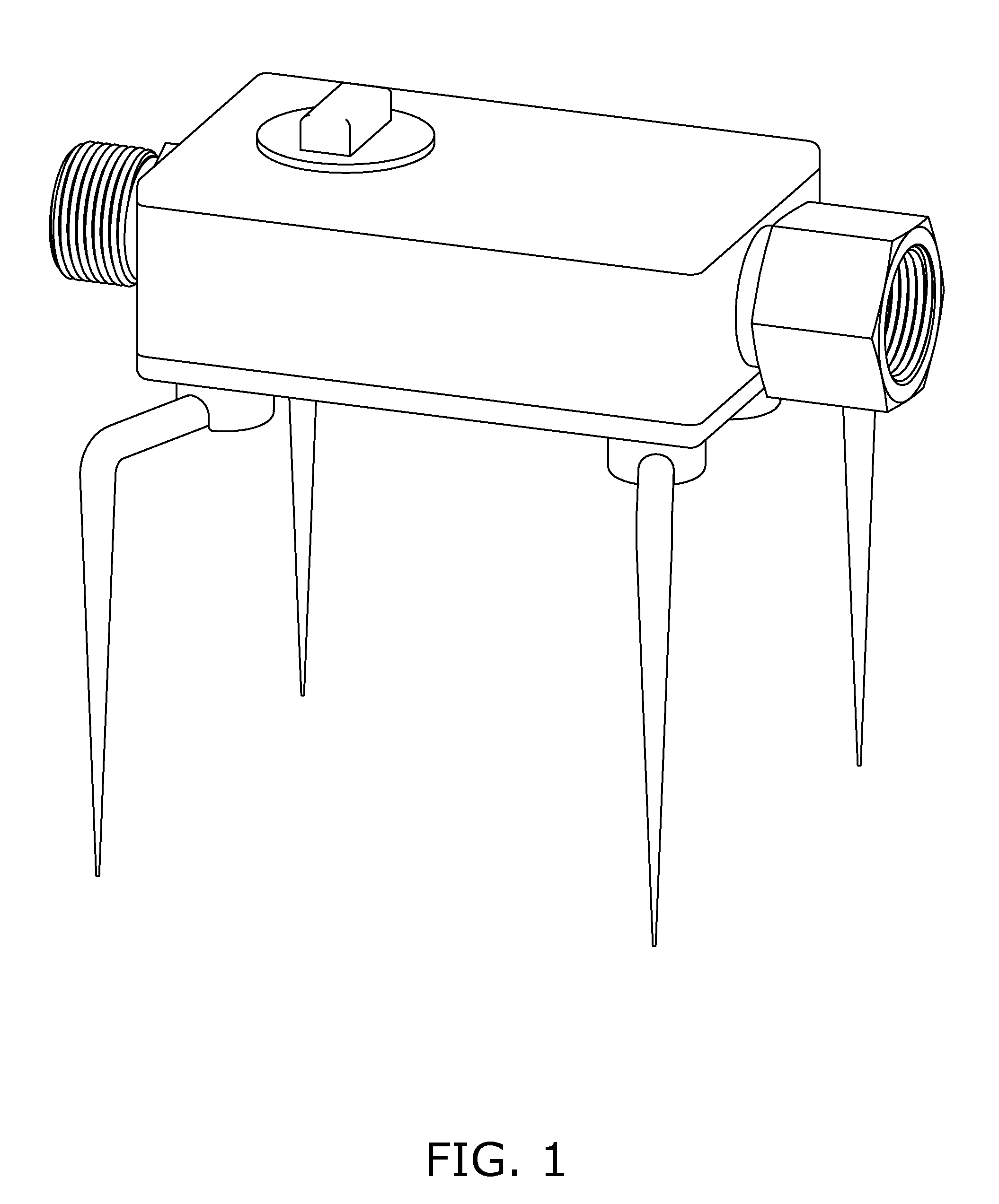
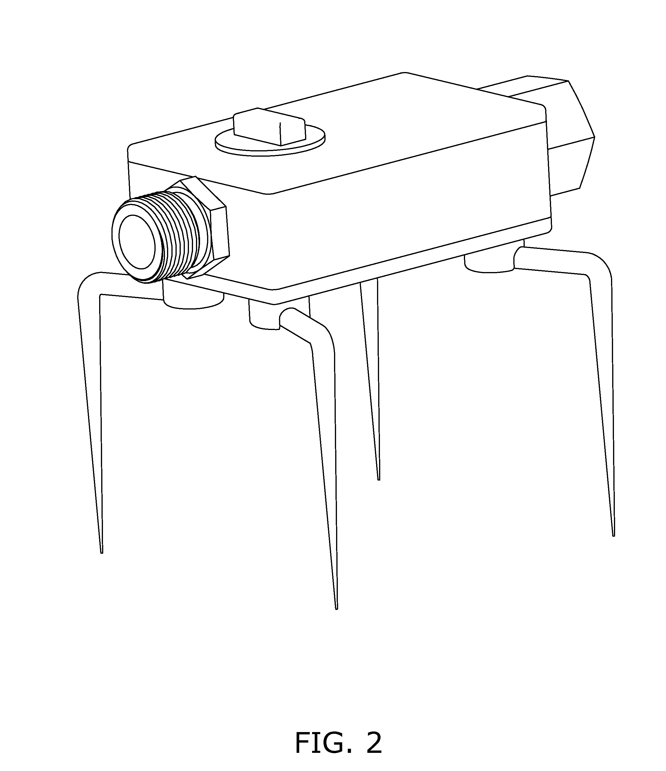
[0050]The following numbers refer to the different items illustrated by the drawings:
[0051]Body (1), Frame (2), Turbine (3), Generator (4), Leg (5), Channel (6), Inlet (7), Outlet (8), Battery (9), Electronic control mechanism (10), Solenoid (11), Valve (12), Attachment of hose to inlet (13), Attachment of hose to outlet (14), Hose from water supply (15), Hose to sprinkler system (16), Valve lever (17), and spring (18) Sensors (19) leg attachment (20) Upper frame plate (21) Lower frame plate (22) Turbine magnets (23) Generator magnets (24).
DETAILED DESCRIPTION OF THE DRAWINGS
[0052]The following description is not to be taken in a limiting sense, but is made merely for describing the general purposes of the invention. The scope of the invention should be determined with reference to the claims. The present embodiments and examples address the problems described in the background, while also addressing additional problems, as will be seen from the following detailed description.
[0053]...
PUM
Abstract
Sprinkler control units, that are designed to control water usage in residential and commercial above ground sprinkler systems, are disclosed herein. The sprinkler control units operate with any above-ground sprinkler system. They require reduced external power, and use the water flowing through the device to generate power. and are powered by the water flowing through the module. The modules are built with buried sensors that measure the ground saturation level, thus altering the water supply provided through the sprinkler system(s).
Application Information
Patent Timeline
Application Date:The date an application was filed.
Publication Date:The date a patent or application was officially published.
First Publication Date:The earliest publication date of a patent with the same application number.
Issue Date:Publication date of the patent grant document.
PCT Entry Date:The Entry date of PCT National Phase.
Estimated Expiry Date:The statutory expiry date of a patent right according to the Patent Law, and it is the longest term of protection that the patent right can achieve without the termination of the patent right due to other reasons(Term extension factor has been taken into account ).
Invalid Date:Actual expiry date is based on effective date or publication date of legal transaction data of invalid patent.

