
Display apparatus, driving method thereof and electronic equipment

a technology of display apparatus and driving method, which is applied in the direction of electric digital data processing, instruments, computing, etc., can solve the problems of insufficient dynamic range for gradation display of liquid crystal cells, large power consumption, and difficult to reduce power consumption, so as to optimize both white luminance and black luminance, the effect of reducing the amount of electric power

Active Publication Date: 2009-03-05
JAPAN DISPLAY INC
View PDF3 Cites 17 Cited by
  • Summary
  • Abstract
  • Description
  • Claims
  • Application Information

AI Technical Summary

Benefits of technology

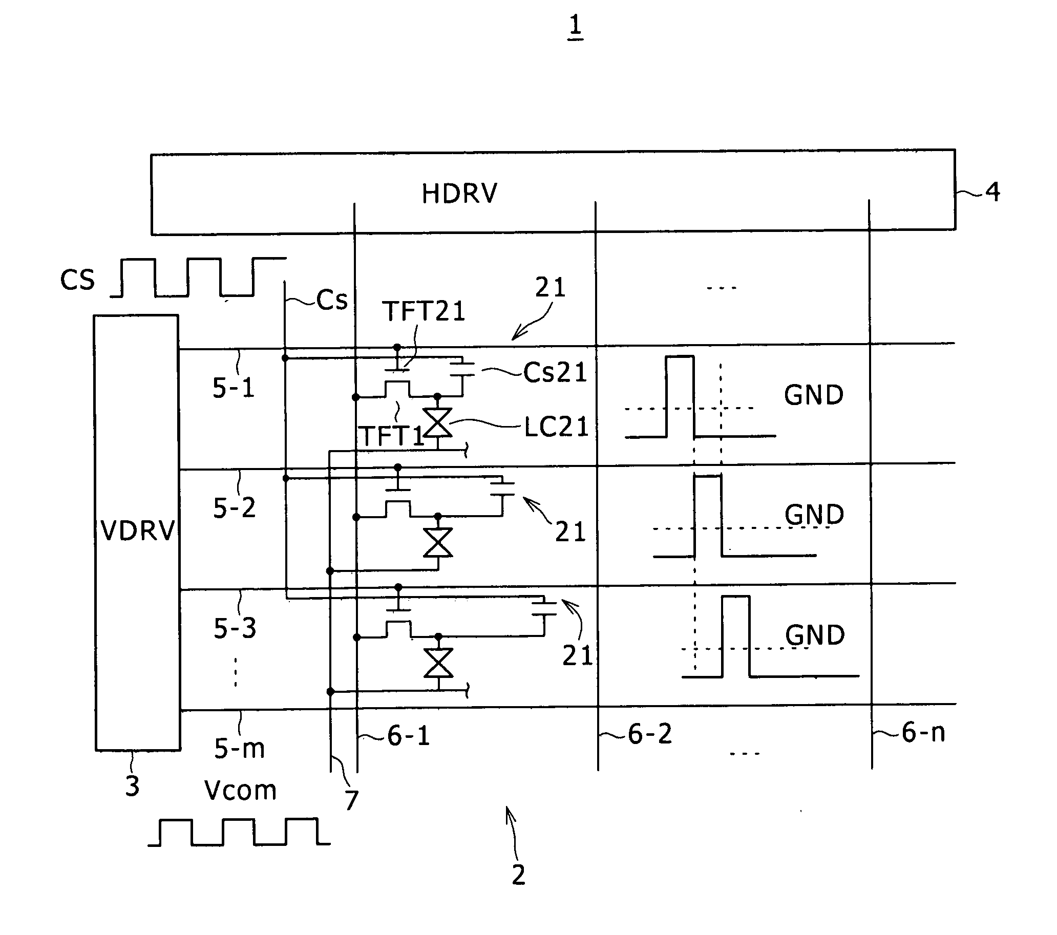
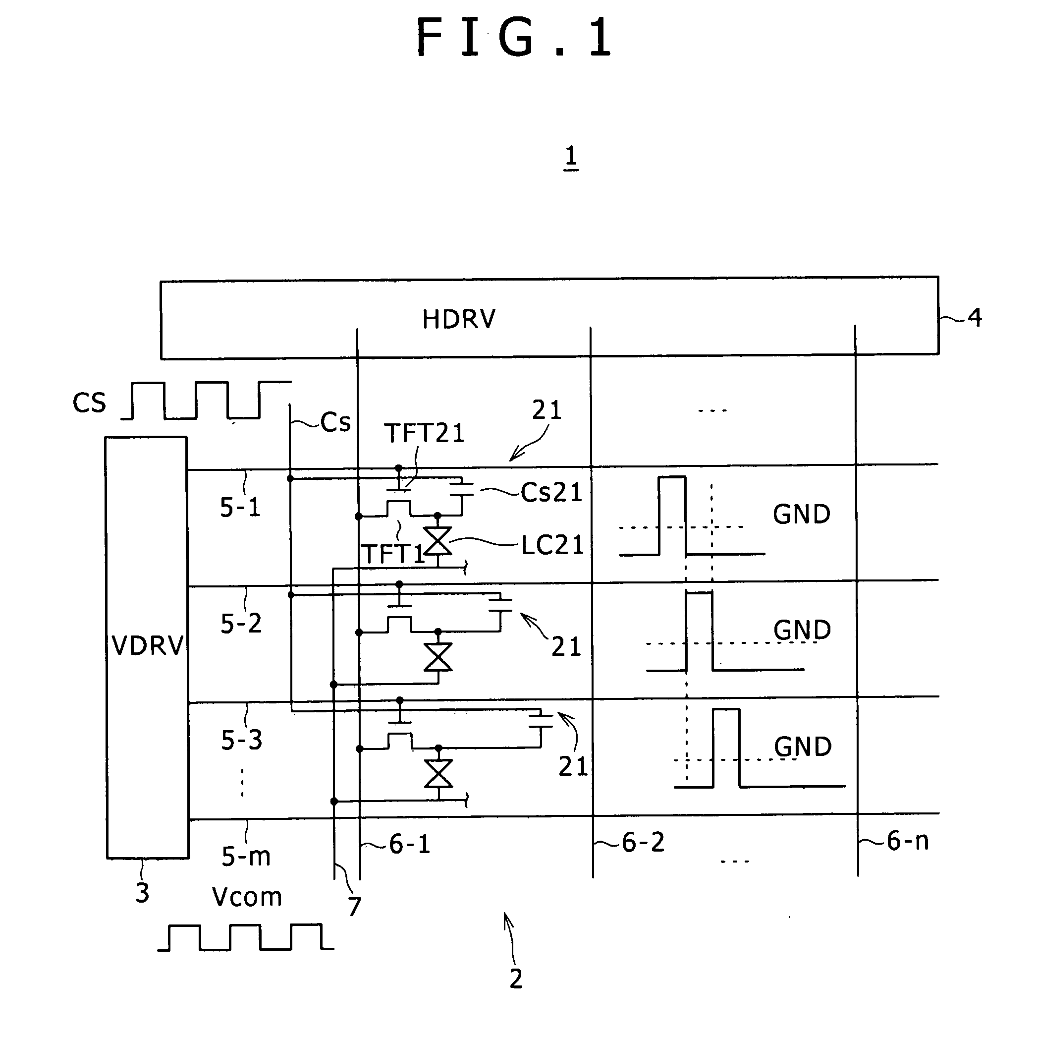
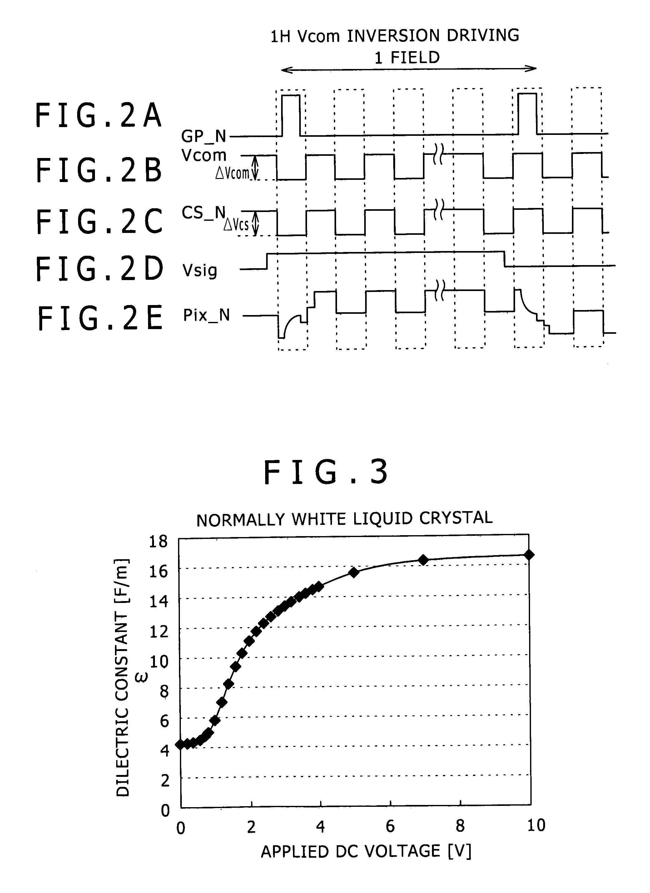
[0020]On top of that, in comparison with the 1H Vcom inversion driving method, the capacitive coupling driving method cited above has characteristic advantages such as an improved liquid-crystal response speed due to the so-called over drive operation, fewer audio noises generated in a Vcom frequency band and a capability of compensating the contrast in a high-definition display panel.
[0026]Addressing the problems described above, inventors of the present invention have innovated a liquid-crystal display apparatus capable of reducing the amount of power consumed in the liquid-crystal display panel as well as optimizing both the white luminance and the black luminance and innovated a driving method to be adopted by the display apparatus.
[0066]The embodiments of the present invention offers merits of a capability of reducing the amount of electric power consumed by the liquid-crystal display panel as well as a capability of optimizing both the white luminance and the black luminance.

Problems solved by technology

If the received liquid-crystal voltage has a level in the range zero to 3.5 V, however, even though a dynamic range for the gradation display of the liquid-crystal cell can be obtained, the power consumption is large.
That is to say, it is more difficult to make an effort to reduce the power consumption.
If the voltage is simply reduced, however, there will be cases in which a sufficient dynamic range for the gradation display of the liquid-crystal cell cannot be obtained.

Method used


Image

  • Display apparatus, driving method thereof and electronic equipment
  • Display apparatus, driving method thereof and electronic equipment
  • Display apparatus, driving method thereof and electronic equipment

Examples


Embodiment Construction

[0136]Preferred embodiments of the present invention are explained in detail by referring to diagrams as follows.

[0137]FIG. 4 is a diagram showing a typical configuration of an active-matrix display apparatus 100 implemented by an embodiment of the present invention as a display apparatus employing, for example, a liquid-crystal cell as a display element (also referred to as an electro optical device) in each pixel circuit. FIG. 5 is a circuit diagram showing a typical concrete configuration of an effective pixel section 101 of the active-matrix display apparatus 100 shown in FIG. 4.

[0138]As shown in FIGS. 4 and 5, the active-matrix display apparatus 100 has main components including the effective pixel section 101, a vertical driving circuit (V / CSDRV) 102, a horizontal driving circuit (HDRV) 103, gate lines (each also referred to as a scan line) 104-1 to 104-m, capacitor lines 105-1 to 105-m, signal lines 106-1 to 106-n, a first monitor (dummy) pixel section (MNTP1) 107-1, a second...


PUM


Abstract

A display apparatus including: an effective pixel section having a plurality of pixel circuits arranged to form a matrix, each pixel circuit including a switching device through which pixel video data is written into the pixel circuit; a plurality of scan lines each provided for an individual one of rows of the pixel circuits arranged on the effective pixel section to control the conduction states of the switching devices; a plurality of capacitor lines each arranged for individual one of the rows connected to the pixel circuits; a plurality of signal lines each arranged for individual one of columns connected to the pixel circuits to propagate the pixel video data; a first driving circuit configured to selectively drive the scan lines and the capacitor lines; and a second driving circuit configured to drive the signal lines.

Description

CROSS REFERENCES TO RELATED APPLICATIONS[0001]The present invention contains subject matter related to Japanese Patent Application JP 2007-224924 filed in the Japan Patent Office on Aug. 30, 2007, the entire contents of which being incorporated herein by reference.BACKGROUND OF THE INVENTION[0002]1. Field of the Invention[0003]The present invention relates to an active-matrix display apparatus having display elements each included in one of pixel circuits arranged on a display area to form a matrix, a driving method to be adopted by the display apparatus and electronic equipment employing the display apparatus. In the following description, each of the display elements is also referred to as an electro-optical device.[0004]2. Description of the Related Art[0005]An example of the display apparatus is a liquid-crystal display apparatus employing liquid-crystal cells as display elements, each of which is referred to as an electro-optical device. The liquid-crystal display apparatus is ...

Claims


Application Information

Patent Timeline
Patent Type & Authority Applications(United States)
IPC IPC(8): G09G3/36
CPCG09G3/3614G09G2320/029G09G2300/0876G09G3/3655
Inventor TOMOHIRO, KAZUHISAMURASE, MASAKINAKANISHI, TAKAYUKIITAKURA, NAOYUKIKIDA, YOSHITOSHI
Owner JAPAN DISPLAY INC
Learn More