Industrial truck, method and computer program for controlling an industrial truck

a technology for industrial trucks and computer programs, applied in the field of industrial trucks, can solve the problems of vital stability of trucks and increase the wear of trucks, and achieve the effect of reducing the maximum allowed acceleration of load supporting members

Active Publication Date: 2015-09-22
BT PROD
View PDF25 Cites 4 Cited by
  • Summary
  • Abstract
  • Description
  • Claims
  • Application Information

AI Technical Summary

Benefits of technology

[0006]The object of the present invention is solved by providing an industrial truck comprising a truck body and a load supporting member that is movable in a vertical and a horizontal direction. The truck is adapted to reduce the maximum allowed acceleration of the load supporting member in the vertical direction when the load supporting member is located at specific horizontal positions in relation to the truck body.
[0011]Unfortunately, the maximum values of 2) and 3) coincide; the horizontal acceleration reaches a top value when the load supporting member turns in its slewing horizontal motion, at this turning point the lever is also the largest. Since these effects are increased when the load supporting member is located at specific horizontal positions in relation to the truck body, the invention proposes reducing the vertical acceleration of the load supporting member when located at such horizontal positions.
[0012]Said decrease of the vertical acceleration improves truck stability and reduces mast stress. The invention also provides easier operation of the truck, since an operator need not consider the current horizontal position of the load supporting member and on occasion, i.e. at specific horizontal positions, make an effort to move the load gently in the vertical direction.
[0013]The load supporting member may be movable between an innermost horizontal position and an outermost horizontal position. The innermost horizontal position corresponds to the load supporting member being located closest to the centre of gravity of the truck body, and the outermost horizontal position corresponds to the load supporting member being located furthest away from the centre of gravity of the truck body. In this connection, the truck may be adapted to reduce said vertical acceleration when the load supporting member is located a distance away from said innermost horizontal position. During normal operation, most of the material handling is performed with the load supporting member located at the innermost position, i.e. closest to the truck body. The load supporting member is normally only displaced away from the truck body when load is picked up or delivered. Thus, by reducing the vertical acceleration when the load supporting member is located a distance away from the innermost horizontal position, most of the material handling can be carried out efficiently at normal vertical acceleration, and the vertical acceleration is only reduced when appropriate.
[0017]By reducing not only the maximum allowed vertical acceleration of the load supporting member, but also the maximum allowed vertical speed, it can be ensured that the vertical movement of the load supporting member can be quickly stopped at any time. Attempts have shown that suitable reduction of the maximum allowed speed lies in the range of 60-90%, a preferred range being 70-80%.
[0018]The object of the present invention is also solved by a method for controlling an industrial truck comprising a truck body and a load supporting member, wherein the load supporting member is movable in a vertical direction and a horizontal direction in relation to the truck body. The method includes the step of reducing the maximum allowed acceleration of the load supporting member in the vertical direction when the load supporting member is located at specific horizontal positions in relation to the truck body. All advantages described above apply also to this method. The method may also include the step of reducing the maximum allowed speed in the vertical direction. On industrial trucks comprising a computer, the object may also be solved by a computer program which, when executed by a processor means of the industrial truck, causes said industrial truck to perform said method. Thereby, when applicable, the invention may easily be implemented by updating the software of existing trucks, without any structural redesign.

Problems solved by technology

In the area of industrial trucks, which often handle heavy loads, truck stability is a vital issue.
Poor truck stability, especially when goods are handled at relatively high lift heights, may lead to damages due to dropped goods and also incurs increased truck wear.

Method used


Image

  • Industrial truck, method and computer program for controlling an industrial truck
  • Industrial truck, method and computer program for controlling an industrial truck
  • Industrial truck, method and computer program for controlling an industrial truck

Examples


Embodiment Construction

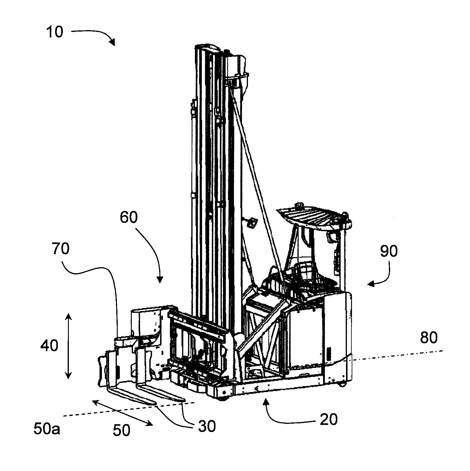
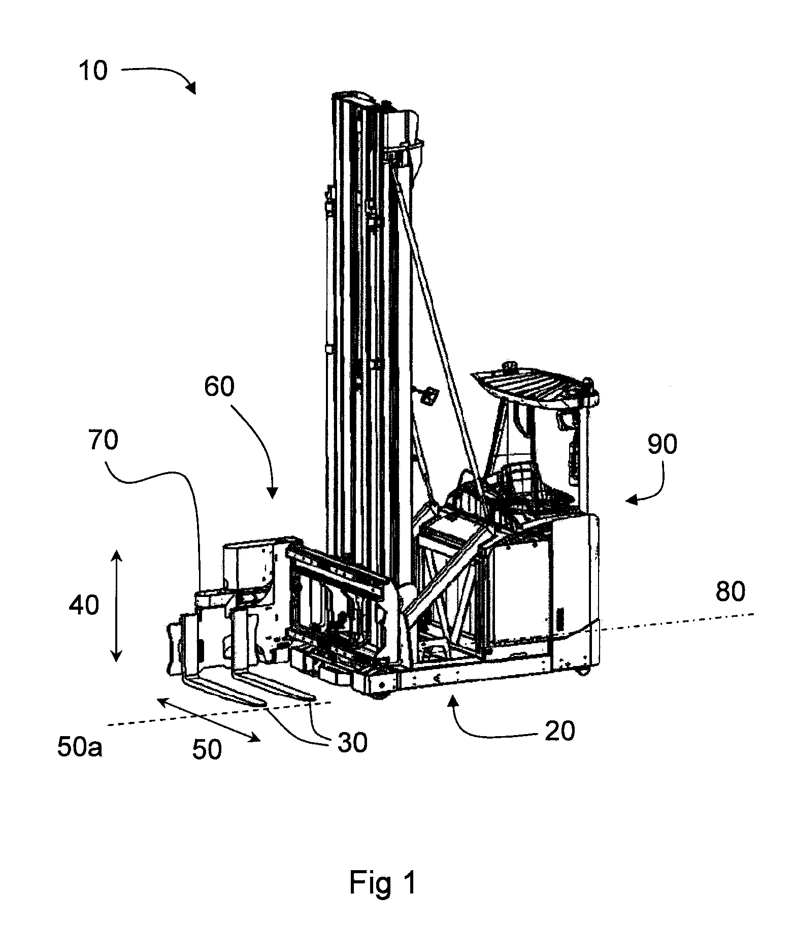
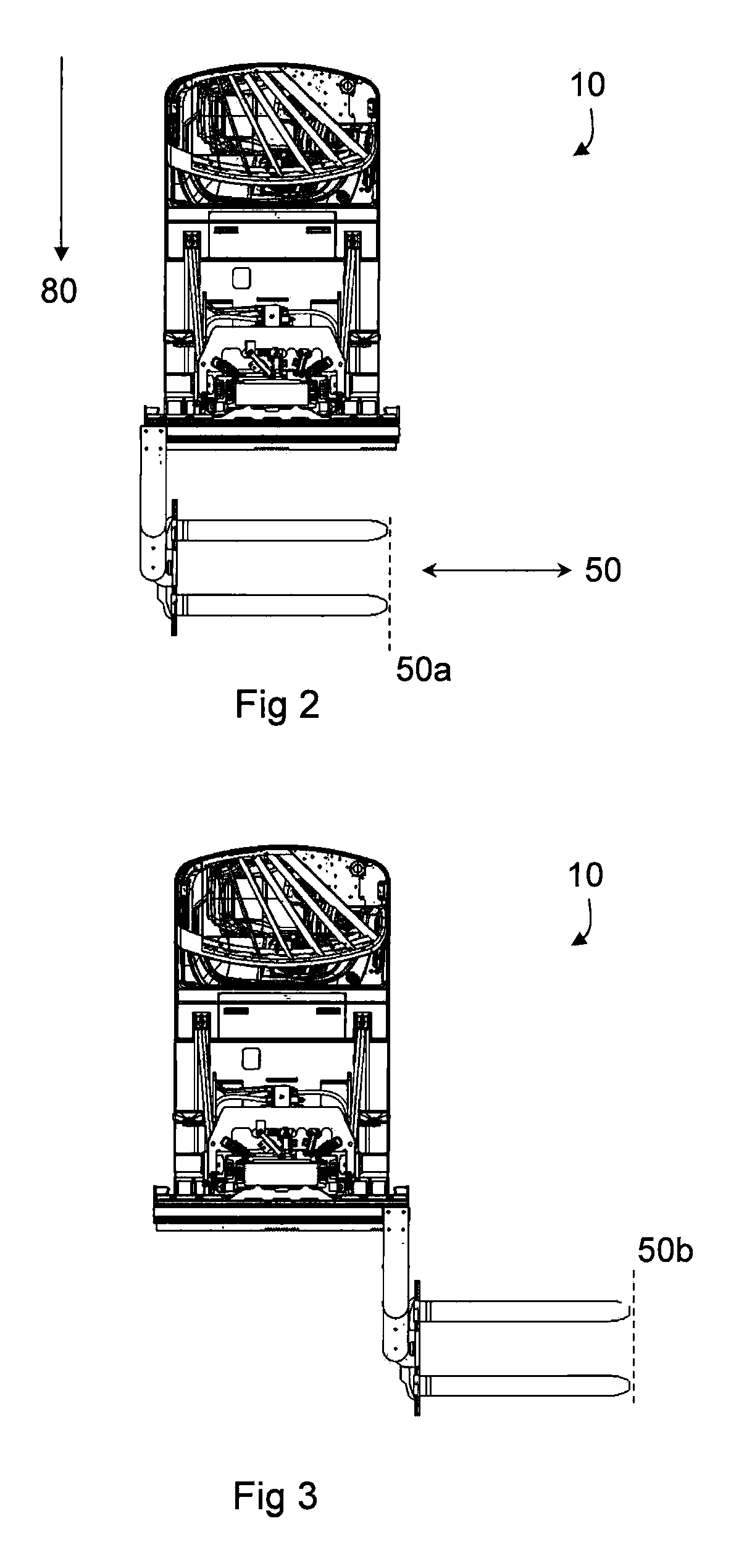
[0024]The present invention is applicable on industrial lift trucks in general. Examples of industrial lift trucks are given in FIGS. 1-4. The same reference numerals apply to equivalent components or components having corresponding functions.

[0025]The invention will first be described with reference to a narrow aisle forklift truck 10 disclosed in FIGS. 1-3. Such a truck 10 comprises a truck body 20 with a motor, a plurality of wheels, a vertically extendable lift mast, a truck computer 90 (not shown in detail) and an operator's compartment. Attached to the lift mast is a load supporting member in the form of a bracket 70 carrying two lift forks 30. The lift forks 30 extend in a horizontal direction 50 which is perpendicular to the longitudinal direction 80 of the truck body 20.

[0026]The bracket 70 with the lift forks 30, hereinafter jointly referred to as forks 30, are movable in a vertical direction 40 and in a horizontal direction 50 in relation to the truck body 20. In this con...


PUM


Abstract

The invention relates to an industrial truck (10; 15) comprising a truck body (20) and a load supporting member (30). The load supporting member (30) is movable in a vertical direction (40) and in a horizontal direction (50; 80) in relation to the truck body (20). According to the invention, the industrial truck (10; 15) is adapted to reduce the maximum allowed acceleration of the load supporting member (30) in the vertical direction (40) when the load supporting member is located at specific horizontal positions in relation to the truck body (20). The invention also pertains to a corresponding method and a computer program.

Description

CROSS-REFERENCE TO RELATED APPLICATIONS[0001]The present application claims the benefit of European Patent Application No. 10189580.3 filed Nov. 1, 2010, which is fully incorporated herein by reference.TECHNICAL FIELD[0002]The present invention assigns to industrial trucks with horizontally movable load supporting members.BACKGROUND ART[0003]In the area of industrial trucks, which often handle heavy loads, truck stability is a vital issue. Poor truck stability, especially when goods are handled at relatively high lift heights, may lead to damages due to dropped goods and also incurs increased truck wear.[0004]Document EP1203745 A1 describes an industrial lift truck having a truck body and a load supporting member that is movable in a vertical direction and in a horizontal direction in relation to the truck body. The truck is adapted to reduce the maximum allowed acceleration of the load supporting member in the horizontal direction when the load supporting member carries heavy load ...

Claims


Application Information

Patent Timeline
Patent Type & Authority Patents(United States)
IPC IPC(8): B66F17/00B66F9/24B66F9/20B66F9/075
CPCB66F9/24B66F9/0755B66F9/20B66F17/003
Inventor ALVETEG, MAGNUS
Owner BT PROD
Why Eureka
Try Eureka