Clutch arrangement

a technology of clutches and cylinders, applied in the direction of fluid actuated clutches, non-mechanical actuated clutches, clutches, etc., can solve the problems of difficult to prevent an irregular distribution of force perpendicular to the force direction, wear on the friction surface can also be subject to a change, etc., to facilitate the production of clutches and simplify production. , the effect of reducing the variation in the effective friction radius or the effective pressing force radius

Inactive Publication Date: 2015-09-22
ZF FRIEDRICHSHAFEN AG
View PDF15 Cites 0 Cited by
  • Summary
  • Abstract
  • Description
  • Claims
  • Application Information

AI Technical Summary

Benefits of technology

[0014]Embodiment examples of a clutch arrangement are based on the insight that a change in the effective friction radius or effective pressing force radius can be limited in that the change in shape of the spring structure is limited by providing the pressing structure. Due to its inherent ability to change shape and the increase in pressing force typically associated with this, the spring structure which can serve, for example, to improve the engagement behavior of the clutch arrangement makes possible a softer engagement, but the change in shape of the spring structure often leads precisely to the above-described change in the effective friction radius. Accordingly, the pressing structure of the pressing element in particular makes it possible to limit the change in friction radius by limiting the change in shape of the spring structure responsible for this, but without significantly impairing the engagement behavior of the clutch arrangement by dispensing with the spring structure and / or without requiring substantial additional installation space along the axis of rotation (axial direction).
[0042]In one embodiment with the first pressing surfaces and second pressing surfaces described above, the first pressing surface and second pressing surface can be formed in such a way that the pressing element contacts the component part substantially along the whole circumference thereof at the level of the effective friction radius thereof when the pressing structure limits the change in shape of the spring structure. A uniform distribution of force along the circumference of the clutch arrangement can be achieved in this way so that variations in the effective friction radius or effective pressing force radius can be reduced along the circumference.

Problems solved by technology

It is precisely in case of sharply diverging rotational speeds such as can occur, for example, during starting, that energy is converted into heat in the area of the relevant friction surfaces, which can lead to an unwanted heating of the relevant friction surfaces or of the relevant component parts.
In reality, it is often difficult to prevent an irregular distribution of force perpendicular to the force direction.
Therefore, as a result of a change occurring in the friction radius during operation, wear on the friction surfaces can also be subjected to a change, for example, a loading of the corresponding components.
These components can also be subjected to other mechanical loads, possibly through additional radially acting forces or force components, which can lead to, or contribute to, unwanted effects.
Accordingly, it may happen that individual components of the clutch tend to tilt during operation.

Method used


Image

  • Clutch arrangement
  • Clutch arrangement
  • Clutch arrangement

Examples


Embodiment Construction

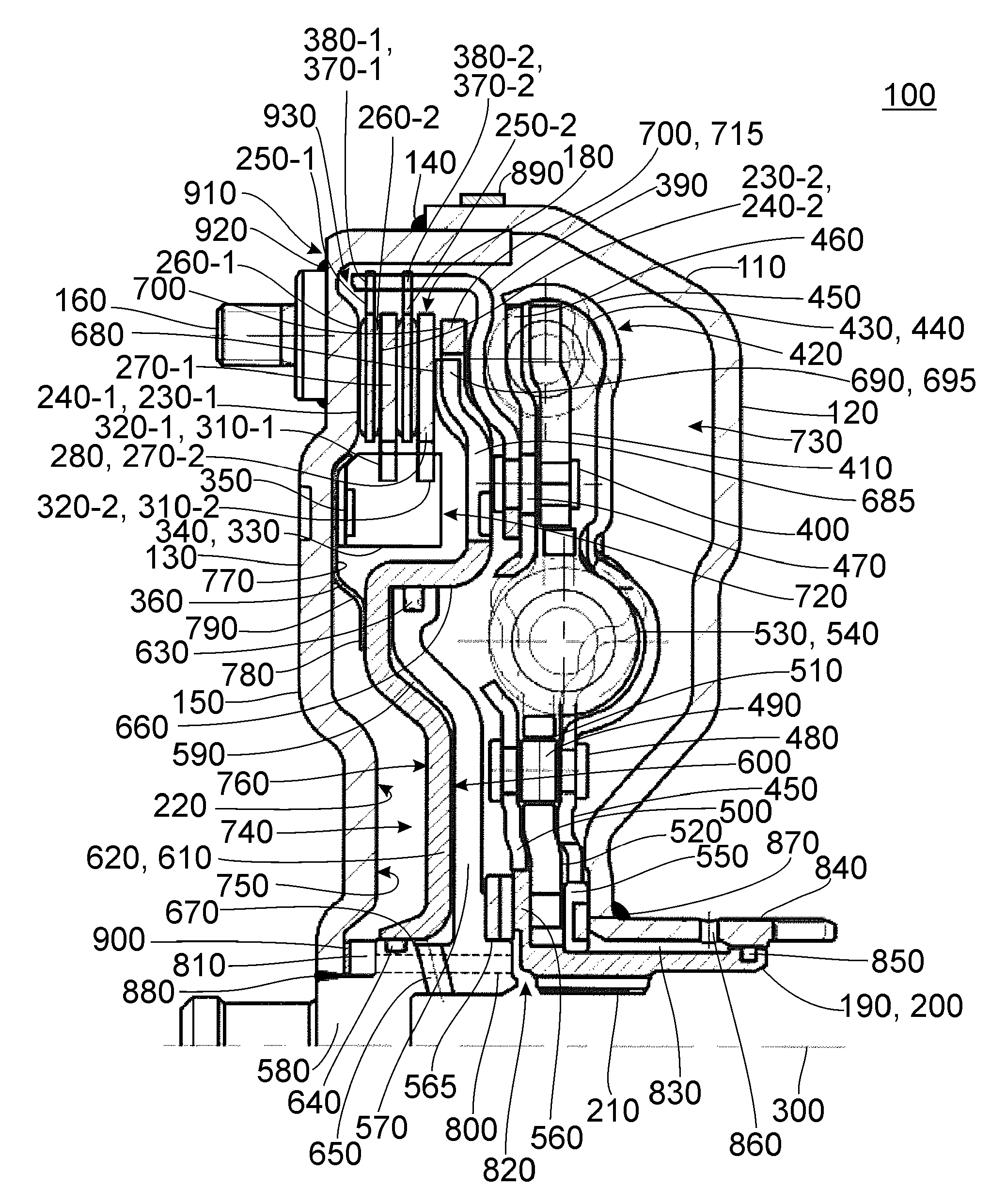
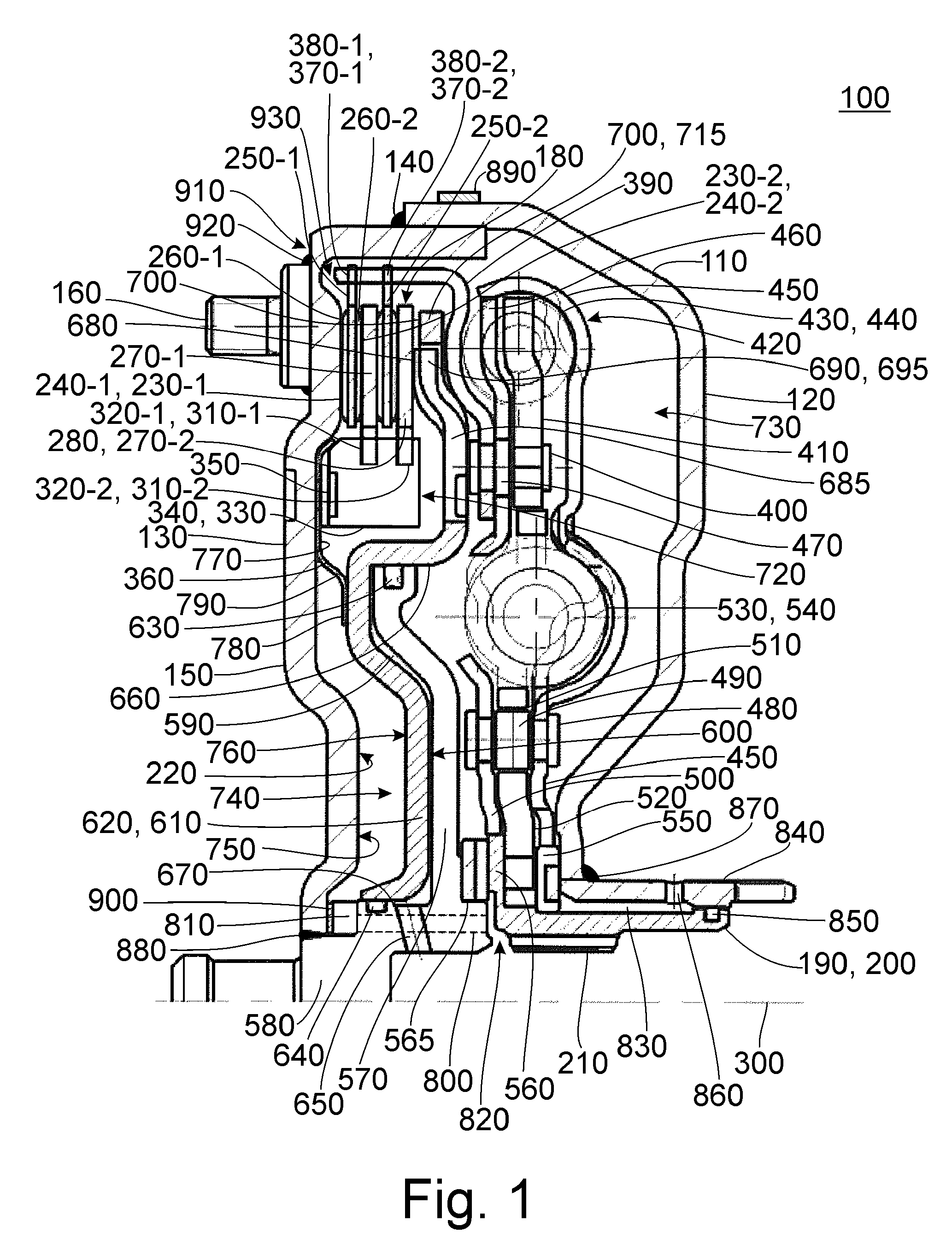
[0062]FIG. 1 shows a cross section through a clutch arrangement 100 according to one embodiment. The clutch arrangement 100 can be used, for example, in a drivetrain of a vehicle, for example, to convey a torque supplied by a drive unit to a transmission or to another component in a separable manner. Therefore, the clutch arrangement 100 can be used, for example, as a separating clutch when combined with a synchronized transmission or as a starting clutch in combination with a non-synchronized transmission, for example, a corresponding automatic transmission.

[0063]Clutch arrangement 100 comprises a housing 110 which is constructed in the present instance as a two-part housing with a first housing shell 120 and a second housing shell 130. The second housing shell 130 is also referred to as engine-side cover of clutch arrangement 100. The two housing shells 120, 130 are connected to each other via a weld connection 140. Housing 110 can accordingly be filled, or is filled, with a fluid...


PUM


Abstract

A clutch arrangement for a drivetrain of a vehicle comprises a first friction surface, a second friction surface and a pressing element. The first and second friction surfaces are arranged to be movable relative to each other along an axis of rotation of the clutch arrangement. The first and second friction surfaces are formed that they can be brought into a frictional engagement with each other to make a torque transmittable from the first friction surface to the second friction surface. One of the first and the second friction surfaces is arranged at a component part. The pressing element comprises a spring structure and is configured to produce or sever the frictional engagement upon actuation by causing a force along the axis of rotation. The spring structure is configured and arranged to at least partially cause the force on the component part through a change in shape.

Description

CROSS-REFERENCE TO RELATED APPLICATIONS[0001]This is U.S. national stage of PCT Application No. PCT / EP2013 / 050194, filed on Jan. 8, 2013, which claims priority to German Patent Application No. DE 10 2012 201 507.8, filed on Feb. 2, 2012, each of which is hereby incorporated in its entirety by reference.FIELD OF INVENTION[0002]The subject matter disclosed in the specification is directed to a clutch arrangement such as can be used, for example, in a drivetrain of a vehicle, for example, of a motor vehicle.DESCRIPTION OF THE RELATED ART[0003]Clutches are used in a wide variety of forms in the vehicle sector, particularly in the motor vehicle sector. They are often utilized within the framework of a drivetrain of a vehicle of the above-mentioned type for transmitting torque and are used, for example, between a drive unit, i.e., an engine, for example, and a downstream transmission. In this way, it is possible to separate the drivetrain such that the engine can continue to run even when...

Claims


Application Information

Patent Timeline
Patent Type & Authority Patents(United States)
IPC IPC(8): F16D43/28F16D13/40F16D25/0635F16D25/12
CPCF16D13/40F16D25/0635F16D25/12F16D25/123
Inventor SCHRODER, ARTHURSUDAU, JORGPITTNER, DANIEL
Owner ZF FRIEDRICHSHAFEN AG
Why Eureka
Try Eureka