Adjustable inside applicator

a technology of applicators and adjusters, which is applied in the direction of brushes, coatings, constructions, etc., can solve the problems of flexible bead flexing and compound cracking

Active Publication Date: 2015-10-06
TAPE PRO DRYWALL TOOLS
View PDF5 Cites 4 Cited by
  • Summary
  • Abstract
  • Description
  • Claims
  • Application Information

AI Technical Summary

Benefits of technology

[0006]The present invention is directed to an adjustable inside applicator, which may at least partially overcome at least one of the abovementioned disadvantages or provide the consumer with a useful or commercial choice.
[0009]In the context of the present specification, the adjustable inside applicator is adapted to apply compound to a joint, by which it is meant that the compound is preferably applied to planar portions of wall beside the apex of the joint, rather than to the entirety of the joint including the apex. This may allow a flexible bead or similar to be positioned at the apex in order to allow for expansion between the two wall portions through movement of the flexible bead. If compound is applied over the top of a flexible bead, there will likely be cracking of the compound when the flexible bead flexes. This can be minimised or avoided by applying the joint compound beside the apex but not over the apex or flexible bead.
[0036]The depressed or rebated portion of each floating application guide head may be shaped in order to provide a particular shape to the compound strip which is dispensed using the applicator. For example, the compound strip may be substantially planar or may have a convex or concave cross-sectional shape depending upon the shape of the depressed or rebated portion. Preferably, the shape of the strip will be substantially planar in order to minimise wastage of the compound.
[0038]Preferably, a mount or seat will be provided on the floating application guide head to mount the biasing member or mechanism and a corresponding mount or seat is provided on the attachment body. The configuration of the mount or seat will be dependent upon the nature of the biasing member or mechanism used. In its simplest form, the biasing member or mechanism will be or include a spring. According to this embodiment, a boss or shaped receiving opening may be provided on each side of the body and a corresponding boss or shaped receiving opening provided on each floating application guide head in order to seat the spring, minimising or preventing movement of the spring in any direction other than the compression or extension direction. This will also preferably act to minimise or prevent dislodgement of the spring at either end.
[0042]An advantage of the spring loaded heads is that they adjust to the angle of the walls. If a fixed applicator head is used on a joint that is different to the angle of the head, it will result in leakage of joint compound and irregular application. If the joint is at anything other than 90° or 135° the compound would likely be applied by hand which is arguably slower.

Problems solved by technology

If compound is applied over the top of a flexible bead, there will likely be cracking of the compound when the flexible bead flexes.

Method used


Image

  • Adjustable inside applicator
  • Adjustable inside applicator
  • Adjustable inside applicator

Examples


Embodiment Construction

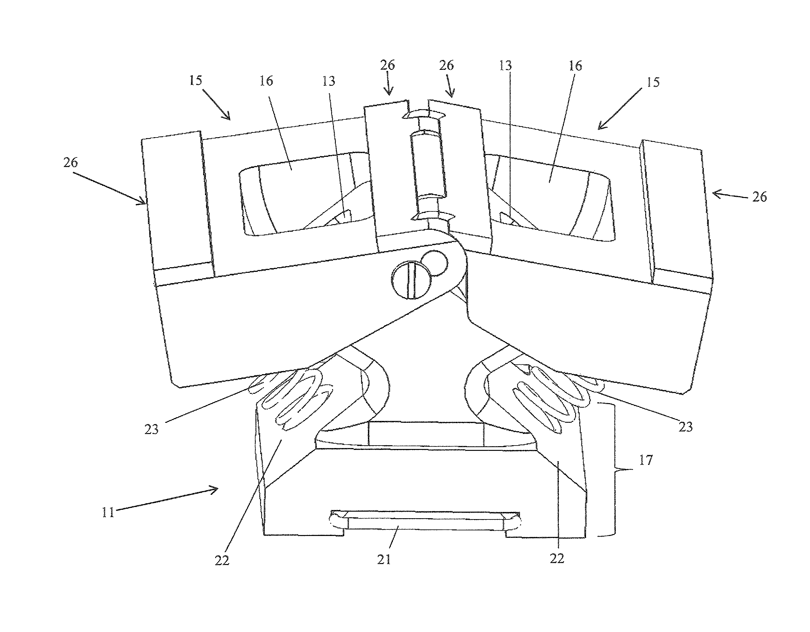
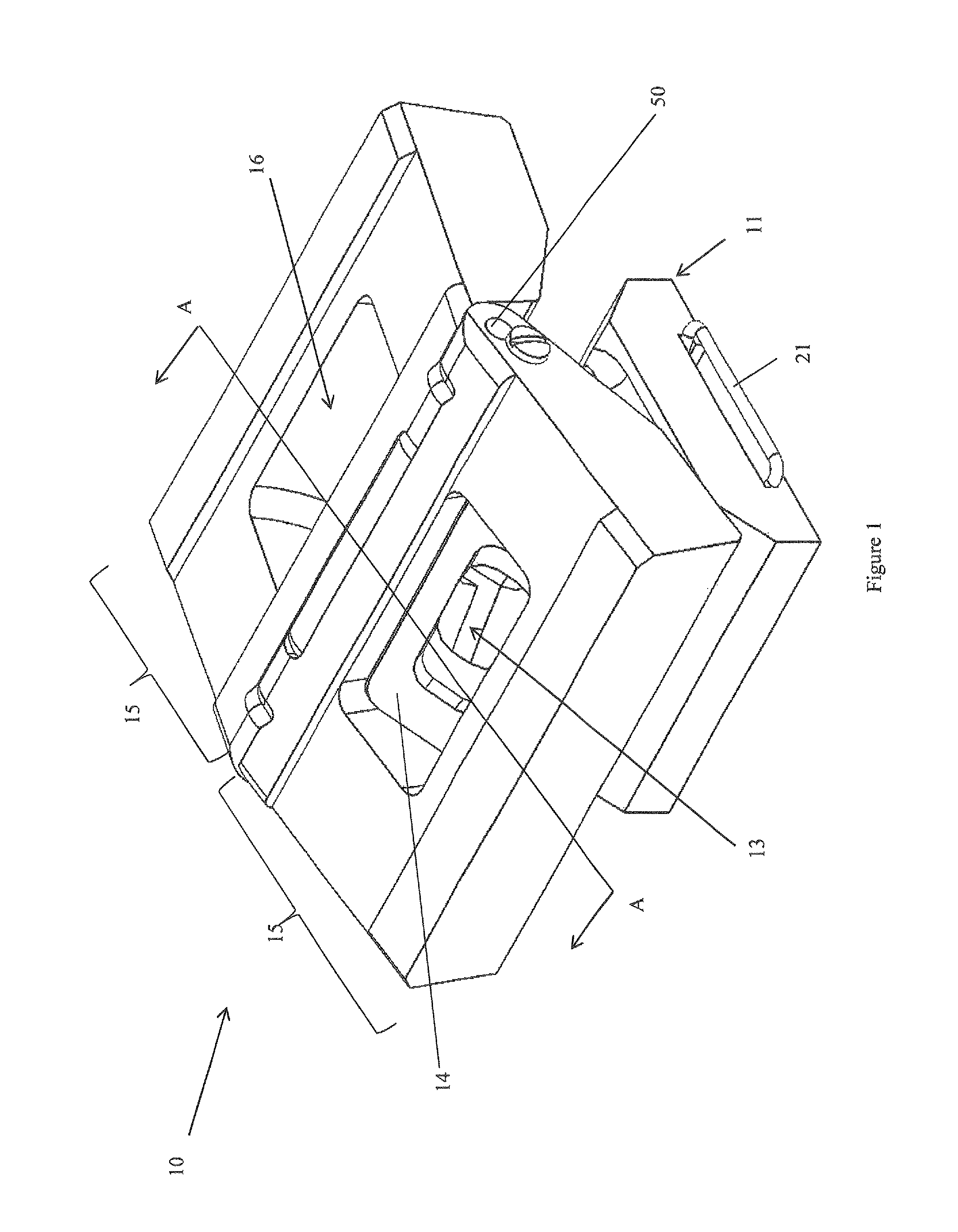
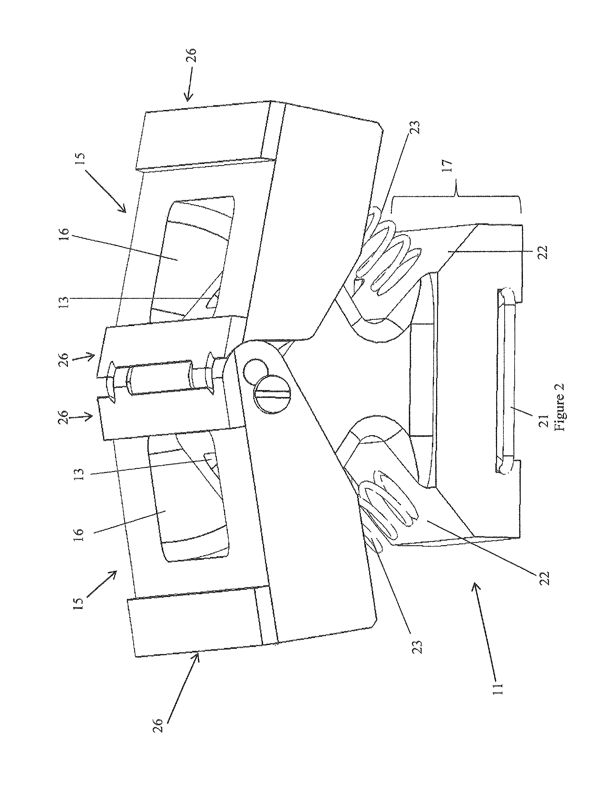
[0054]According to a particularly preferred embodiment of the present invention, an adjustable inside applicator 10 for applying joint compound to a joint between two panels at an angle to one another is provided.

[0055]The adjustable inside applicator 10 of the illustrated embodiment includes an attachment body 11 to attach the applicator 10 to a source of compound to be applied to a joint, the attachment body 11 having a bore including an inlet 12 and at least two outlets 13, a pair of faces 14 angularly disposed relative to one another with at least one outlet 13 located in each of the pair of faces 14, and a pair of floating application guide heads 15 mounted pivotably to the attachment body 11 and biased towards a maximum angle between the floating application guide heads 15 but movable against the bias into an angle which is less than the maximum, each floating application guide head 15 having an opening 16 therein in communication with a respective at least one outlet 13 of th...


PUM


Abstract

An adjustable inside applicator including an attachment body to attach the applicator to a source of compound to be applied to a joint, the attachment body having a bore including an inlet and at least two outlets, a pair of faces angularly disposed relative to one another with at least one outlet located in each of the pair of faces, and a pair of floating application guide heads mounted pivotably to the attachment body and biased towards a straight angle between the floating application guide heads but movable against the bias into an angle which is less than straight, each floating application guide head having an opening therein in communication with a respective at least one outlet of the body.

Description

TECHNICAL FIELD[0001]The present invention relates to hand tools generally and in particular to a hand tool to apply joint compound to a joint with an interior angle between surfaces.BACKGROUND ART[0002]The tools conventionally available for the application of joint compound to a joint with an interior angle between two surfaces include an application hand with a pair of lateral portions which are at a fixed angle relative to one another with that angle matching the angle between the two surfaces. A container or compound tube of joint compound is typically attached to the head and a channel is provided from the opening of the container to an outlet relative to each of the lateral portions to apply the joint compound to both sides and the apex of an internal angle between two surfaces when a horizontally or vertically prior to applying paper tape by hand.[0003]The surfaces to which the joint compound is applied are rarely finished with sufficient precision that the application of the...

Claims


Application Information

Patent Timeline
Patent Type & Authority Patents(United States)
IPC IPC(8): A46B17/02E04F21/08E04F21/165B05C11/00B05C5/00B05C17/005
CPCB05C11/00B05C5/00E04F21/08E04F21/1655B05C17/00516
Inventor GILL, THOMAS CHARLES
Owner TAPE PRO DRYWALL TOOLS
Why Eureka
Try Eureka