
Device for fixedly securing a metallic inlay

a technology of metallic inlay and fixed fixing, which is applied in the field of element inlay, can solve problems such as difficulty in reading decoration, and achieve the effect of improving visual quality and maintaining mechanical resistan

Active Publication Date: 2015-10-06
OMEGA SA
View PDF12 Cites 4 Cited by
  • Summary
  • Abstract
  • Description
  • Claims
  • Application Information

AI Technical Summary

Benefits of technology

The solution improves the visual quality and resistance of metallic decorations by securely embedding them within the bezel, preventing removal without aesthetic modification, while maintaining mechanical resistance and enhancing contrast.

Problems solved by technology

However, this configuration may make it difficult to read the decoration because of altered transmission of the colouring of the deposit but also because of the lack of difference in shade between the sapphire and the deposit.

Method used


Image

  • Device for fixedly securing a metallic inlay
  • Device for fixedly securing a metallic inlay
  • Device for fixedly securing a metallic inlay

Examples


Embodiment Construction

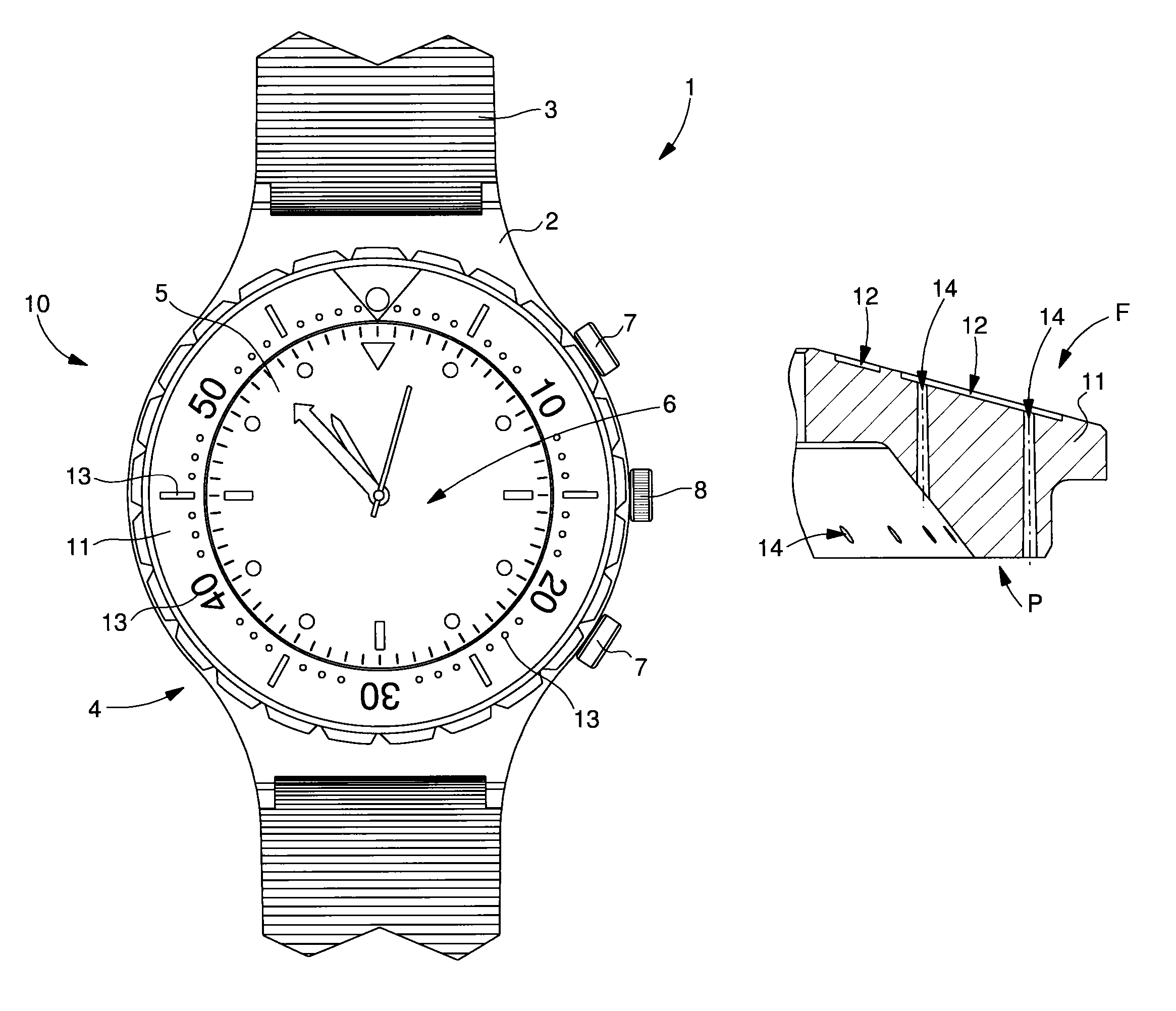
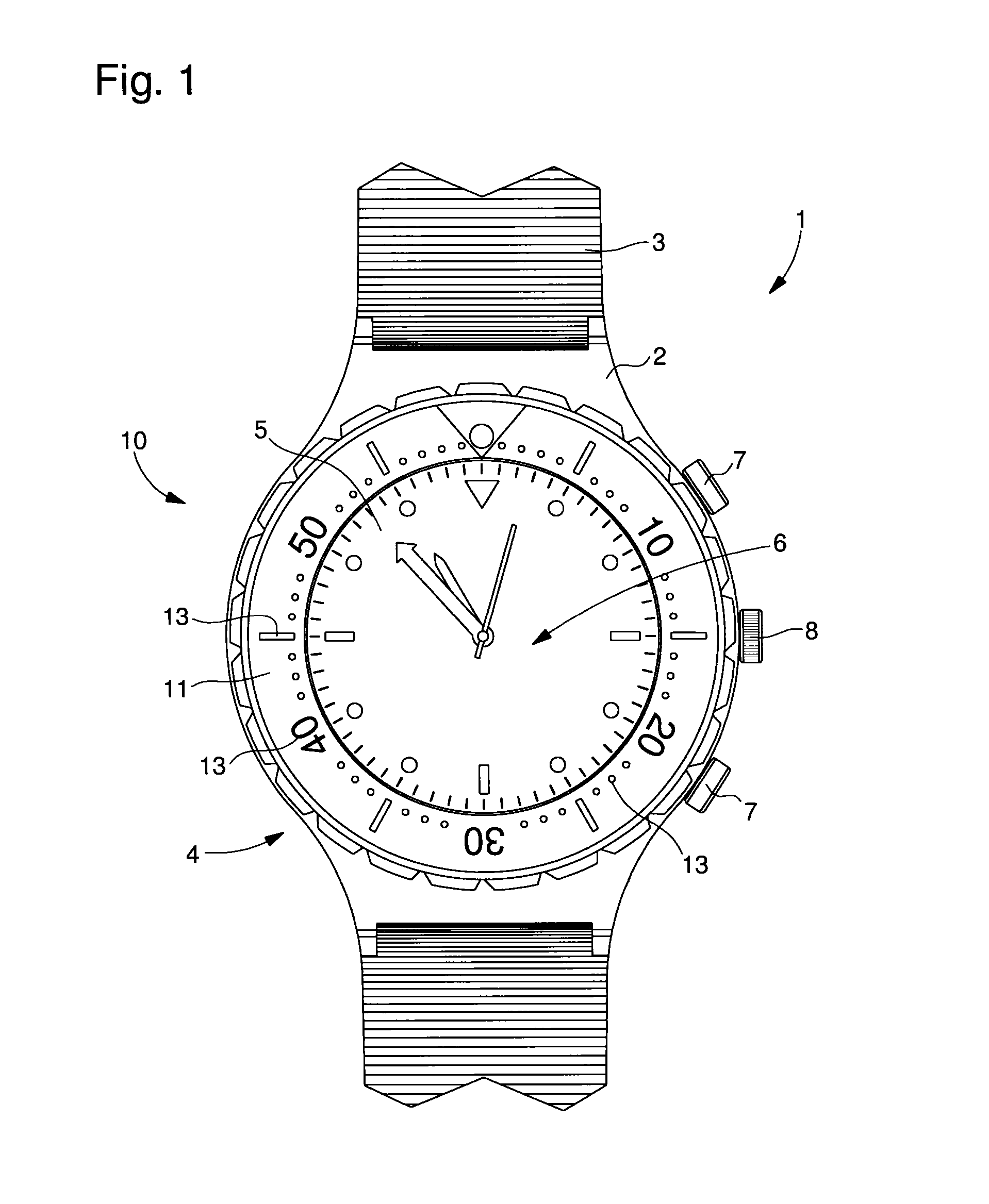
[0041]The example illustrated in FIG. 1 shows a timepiece, generally referenced 1, including at least one inlaid element 10. Each inlaid element 10 is intended to form a part that is very resistant to wear, including at least one metallic decoration 13 whose visual quality is improved, particularly in terms of contrast.

[0042]The inlaid element 10 according to the invention may form either all or part of the external part of timepiece 1. Thus, it could form all or part of a case 2, bracelet 3, bezel 4, dial 5, crystal 6, push button 7 and / or a crown 8. In the example illustrated below, the explanation of the invention will be given with reference to a ring 10 including inlaid decorations 13, forming the scale marks of a bezel 4. It is also possible to form inlaid elements 10 for a timepiece movement such as, for example, a bridge and / or a plate and / or an oscillating weight.

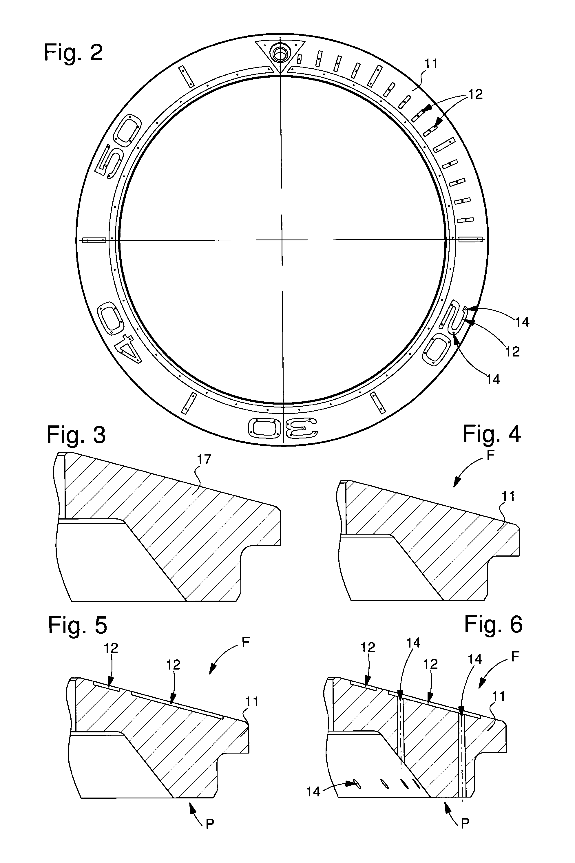
[0043]As illustrated in FIGS. 1, 2 and 8, inlaid ceramic element 10 includes a body 11 including at least one re...


PUM

PropertyMeasurementUnit
depthaaaaaaaaaa
depthaaaaaaaaaa
micro-roughnessaaaaaaaaaa

Abstract

An element including a body including at least one recess forming the pattern cavity for a decoration, the at least one recess being entirely filled by a galvanic deposition in order to form an element inlaid with at least one metallic decoration with improved visual quality. The element includes a device for fixedly securing the at least one metallic decoration communicating with the at least one recess in order to improve the securing of the at least one decoration against said element.

Description

[0001]This application claims priority from European Patent Application No. 12155635.1 filed Feb. 15, 2012, the entire disclosure of which is incorporated herein by reference.FIELD OF THE INVENTION[0002]The invention relates to an element inlaid of at least one metallic decoration and more specifically an element of this type comprising a device for fixedly securing at least one metallic decoration.BACKGROUND OF THE INVENTION[0003]It is known to form watch bezels at least partially made of synthetic sapphire in order to show, through transparency, a deposit plated in a recess underneath the bezel, for example, forming a scale or a brand name. This configuration has the advantage of protecting the deposit from any mechanical degradation by totally covering it with the sapphire part. However, this configuration may make it difficult to read the decoration because of altered transmission of the colouring of the deposit but also because of the lack of difference in shade between the sap...

Claims


Application Information

Patent Timeline
Patent Type & Authority Patents(United States)
IPC IPC(8): G04B19/18G04B37/22G04B45/00C25D5/02B44C1/26
CPCC25D5/02B44C1/26G04B19/18G04B45/00G04B37/226G04B45/0076Y10T428/12063
Inventor NETUSCHILL, ALEXANDREFROELICHER, THOMAS
Owner OMEGA SA
Learn More