Firearm trigger pull training system and methods

Active Publication Date: 2015-10-06
TRIGGERMASTER LLC
View PDF50 Cites 22 Cited by
  • Summary
  • Abstract
  • Description
  • Claims
  • Application Information

AI Technical Summary

Benefits of technology

The present invention provides a trigger pull training system that allows users to see their own trigger pull path and the movement of the barrel during a pull. Users can also record information associated with multiple pulls and display it on a screen in real-time or simultaneously. The system uses an electronic device to monitor the trigger pull path and provides a method for training shooters to improve their trigger pull technique.

Problems solved by technology

First, the operator generally aims the firearm at a target.
Such barrel movement is undesirable and causes inaccuracy of the fired shot.
Similarly, a firearm operator may inadvertently apply force against the trigger using the operator's finger in a third, generally vertical, direction during a trigger pull, causing the firearm barrel to move up or down relative to the desired target.
Such conventional devices and methods, however, do not monitor actual trigger movement in two dimensions and do not correlate trigger pull path to actual barrel displacement.
Moreover, conventional firearm trigger pull monitoring systems also generally measure only the one-dimensional force applied to the trigger as a function of longitudinal position and do not provide a graphical display of two-dimensional trigger pull path.

Method used


Image

  • Firearm trigger pull training system and methods
  • Firearm trigger pull training system and methods
  • Firearm trigger pull training system and methods

Examples


Embodiment Construction

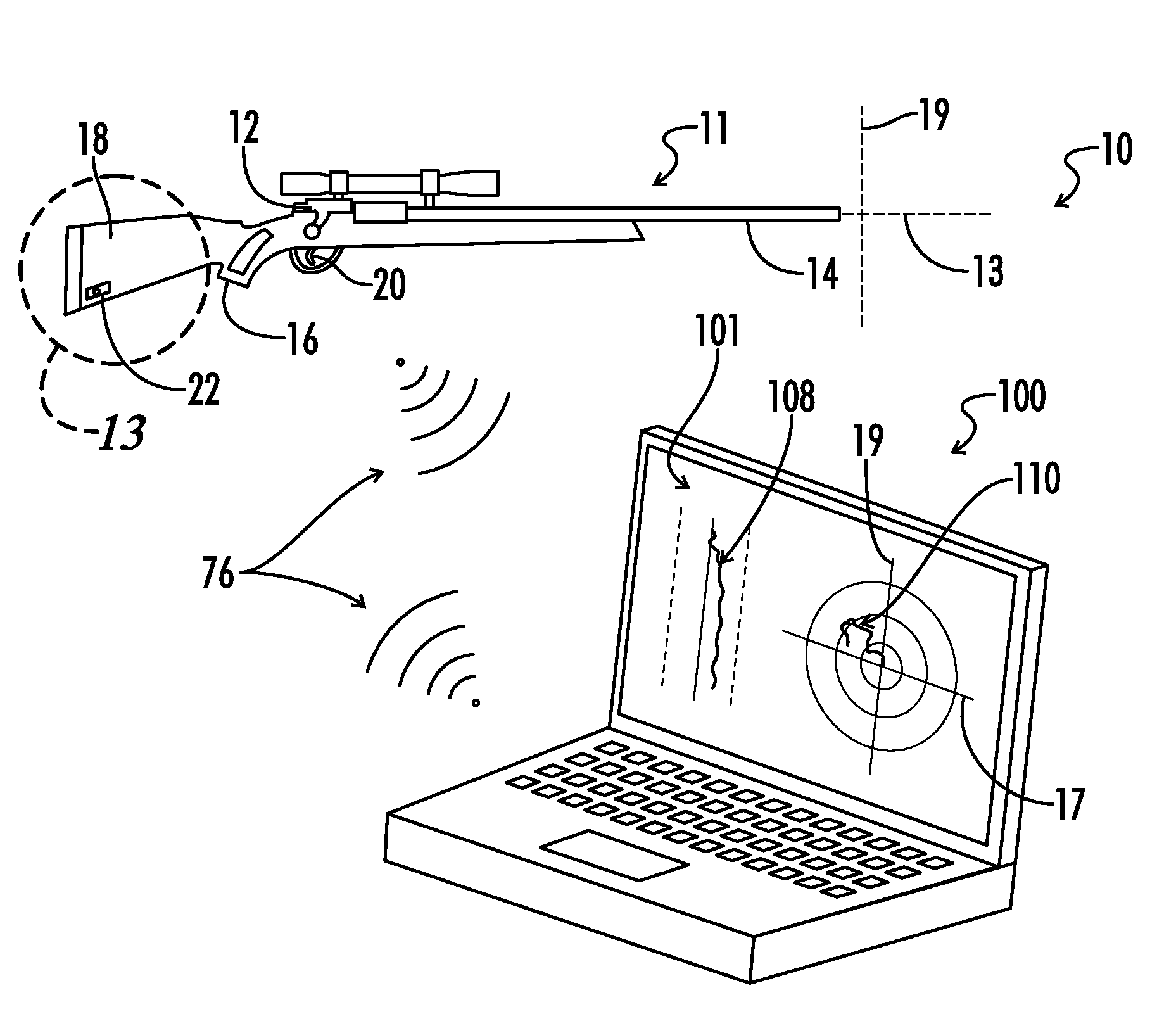
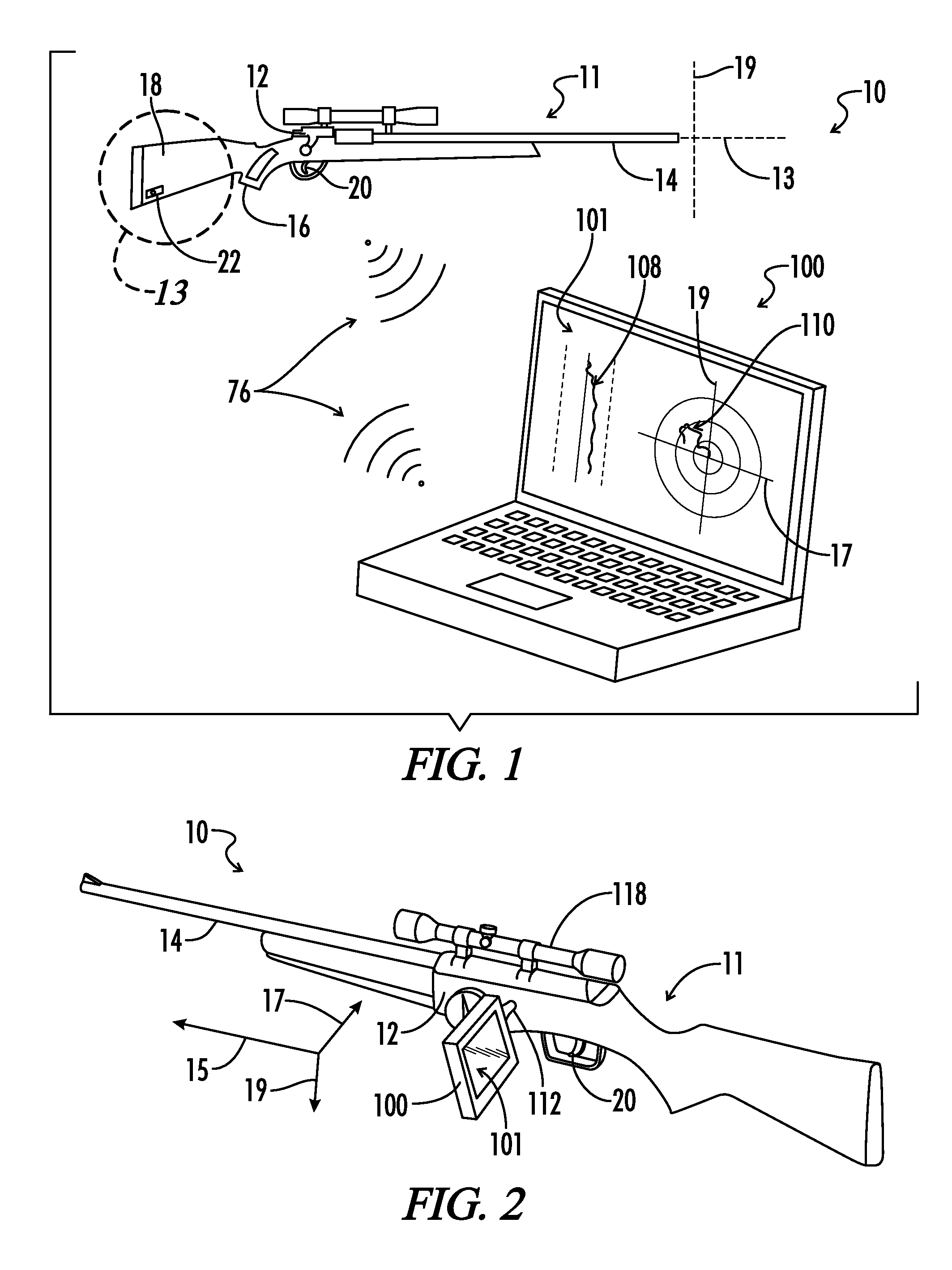
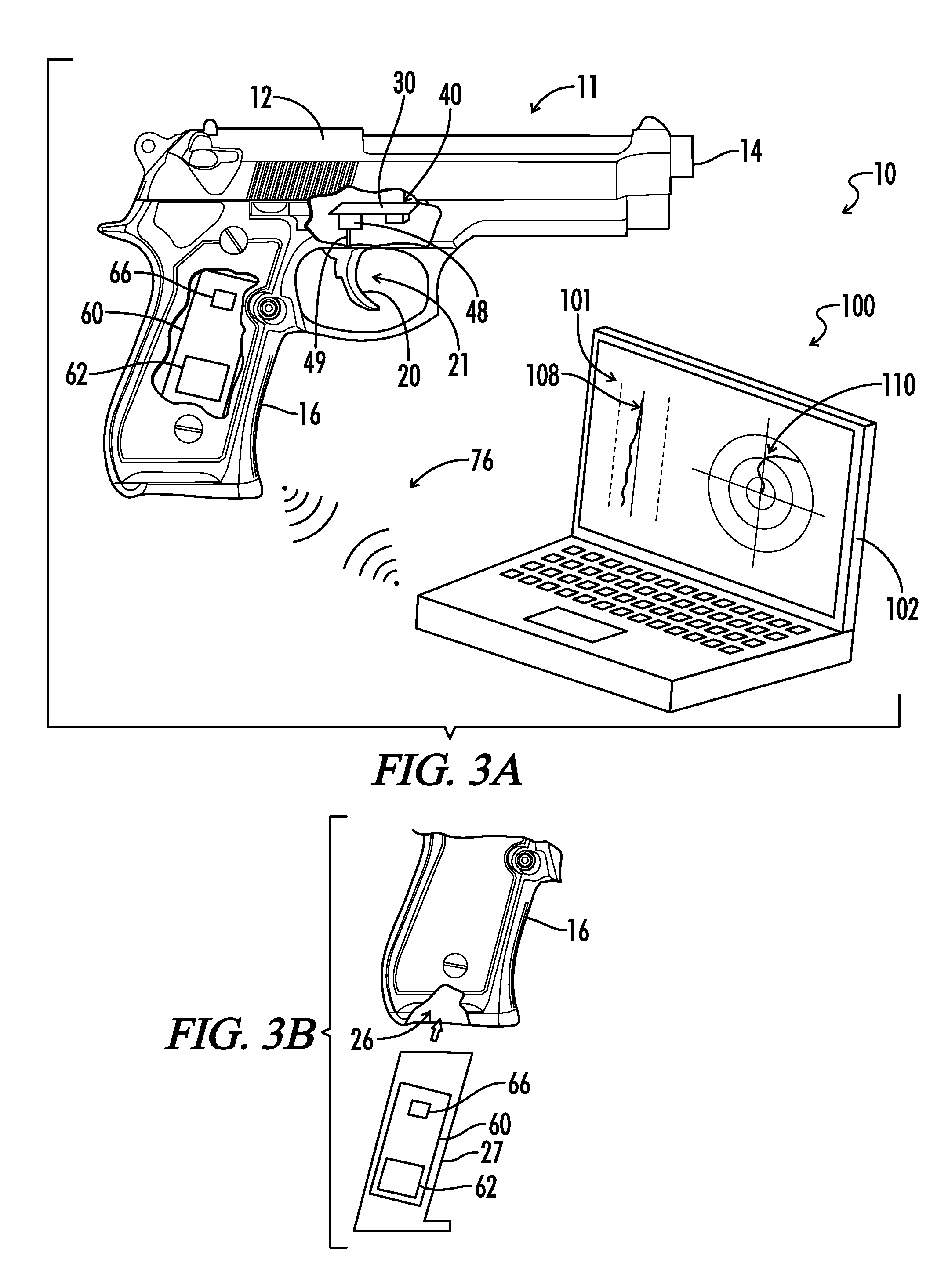
[0041]Referring now to the drawings, FIG. 1 illustrates a perspective view of an embodiment of a firearm system generally designated by the numeral 10. In the drawings, not all reference numbers are included in each drawing for the sake of clarity. In addition, positional terms such as “upper,”“lower,”“side,”“top,”“bottom,” etc. refer to the apparatus when in the orientation shown in the drawing. The skilled artisan will recognize that the apparatus can assume different orientations when in use.

[0042]The firearm system 10 of the present invention generally provides a user the ability to graphically monitor user input to the firearm during or after a live or simulated trigger pull. A trigger pull generally includes the act of depressing, or pulling, the trigger using one or more fingers of the firearm user's hand. In some embodiments, the firearm system 10 allows a firearm user to monitor both the lateral and the longitudinal displacement of the firearm trigger 20 during or after a t...


PUM


Abstract

A firearm training system provides a firearm body having a trigger and a position input circuit. When the trigger is pulled, the position input circuit emits a two-dimensional trigger position signal that allows monitoring of the actual two-dimensional trigger pull path taken by the trigger during the trigger pull. The trigger pull path can be displayed graphically on an electronic device in real time. In other embodiments, the information associated with the trigger position signal can be stored and can be graphically viewed after the trigger pull is complete. The system provides a way to monitor trigger pull path to determine whether the trigger has been pulled laterally. By repeatedly monitoring trigger pulls using the system, a user can train to improve trigger pull technique. Also, a motion sensing circuit disposed on the firearm body can measure movement of the firearm body during the trigger pull, and a barrel displacement indicator can be graphically and numerically displayed on the electronic device corresponding to the actual barrel displacement. A method of providing firearm user input information to a user is also provided.

Description

CROSS REFERENCE TO RELATED APPLICATION[0001]This application is a continuation-in-part of co-pending U.S. patent application Ser. No. 11 / 504,313, filed Aug. 15, 2006, entitled “Shooting Training Device”, all of which is incorporated by reference herein.BACKGROUND[0002]The present invention relates to firearms and more particularly to devices, systems and methods for use with a firearm or a firearm replica for graphically indicating information to a user during or after live or practice firing.[0003]A firearm operator typically provides at least two types of input when operating a firearm. First, the operator generally aims the firearm at a target. Second, the operator typically pulls the firearm trigger using a single finger of the user's hand, thereby activating a firing mechanism in the firearm to discharge one or more projectiles from the firearm barrel toward the target. In some applications, a third type of user input includes applying force to the barrel to keep the barrel ste...

Claims


Application Information

Patent Timeline
IPC IPC(8): F41A33/02F41A19/10F41J5/02F41J5/08F41G1/38F41B11/57F41G3/26
CPCF41A33/02F41A19/10F41B11/57F41G1/38F41G3/2655F41G3/2605A63F2300/8076F41J5/08F41J5/02F41A19/09F41G3/26F41B11/71F41A33/00A63F13/00
Inventor BAXTER, MALCOLM
Owner TRIGGERMASTER LLC
Why Eureka
Try Eureka