High efficiency motorized roller screen and method of operation
What is AI technical title?
AI technical title is built by PatSnap AI team. It summarizes the technical point description of the patent document.
a high-efficiency, roller screen technology, applied in the direction of motor/generator/converter stopper, motor/generator/converter control, instruments, etc., can solve the problems of expensive electrical work or unsightly exposed wires, hard-wiring often requires advanced planning, and battery-powered systems
Active Publication Date: 2015-10-06
THE WATT STOPPER
View PDF102 Cites 24 Cited by
Summary
Abstract
Description
Claims
Application Information
AI Technical Summary
This helps you quickly interpret patents by identifying the three key elements:
Problems solved by technology
Method used
Benefits of technology
Problems solved by technology
While manual operation is effective, in many applications it is undesirable as it is inconvenient to manually operate the system.
In addition, it may be aesthetically displeasing to have cords hanging down from the system in certain applications.
While these systems are effective, they have their disadvantages as the requirement for hard-wiring often requires advanced planning, expensive electrical work or unsightly exposed wires.
Unfortunately, these battery-powered systems suffer from many drawbacks, including, for example, high levels of self-generated noise, inadequate battery life, inadequate or nonexistent counterbalancing capability, inadequate or nonexistent manual operation capability, inconvenient installation requirements, and the like.
Limit switches have inherent drawbacks as they can be expensive and can fail over time.
External limit switches are typically installed during the installation which can be time consuming whereas internal limit switches are installed into the control system of the shade or blind and can be operated by lead screws and nuts or cams also adding cost.
Typical drawbacks to hard stops include the noise, the wear and tear on the components and in the case of battery power supplies and the use of additional current to stall the motor which shorten the battery life.
Method used
Image
Click on the blue label to locate the original text in one second.
Reading with bidirectional positioning of images and text.
Examples
Embodiment Construction
[0063]The invention will now be described with reference to the drawing figures, in which like reference numerals refer to like parts throughout. The term “shade” as used herein describes any flexible material, such as a shade, a curtain, a screen, etc., that can be deployed from, and retrieved onto, a storage tube.
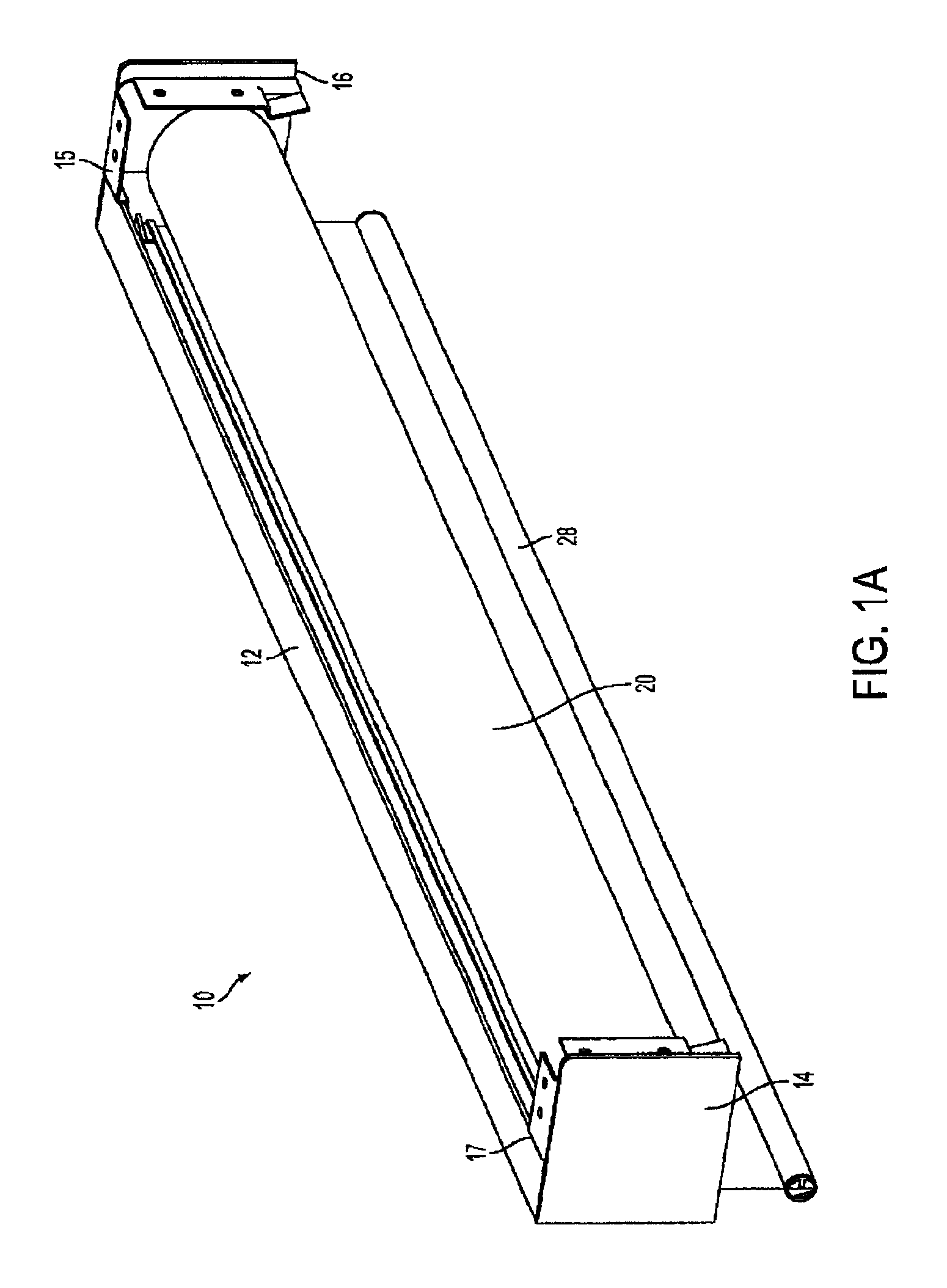
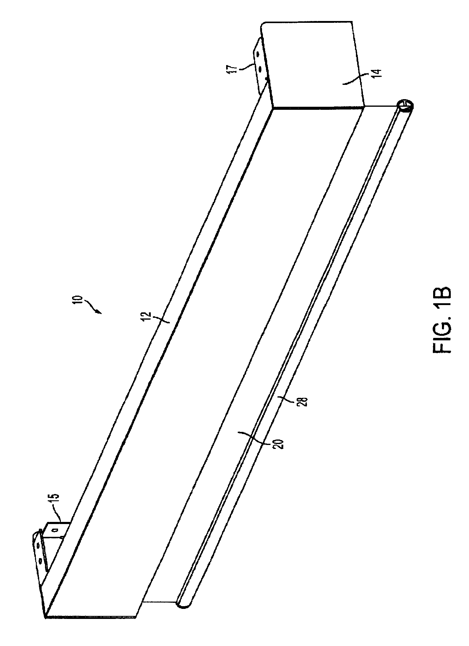
[0064]Embodiments of the present invention provide a remote controlled motorized roller shade in which the batteries, DC gear motor, control circuitry are entirely contained within a shade tube that is supported by bearings. Two support shafts are attached to respective mounting brackets, and the bearings rotatably couple the shade tube to each support shaft. The output shaft of the DC gear motor is fixed to one of the support shafts, while the DC gear motor housing is mechanically coupled to the shade tube. Accordingly, operation of the DC gear motor causes the motor housing to rotate about the fixed DC gear motor output shaft, which causes the shade tube to rotate about...
PUM
Abstract
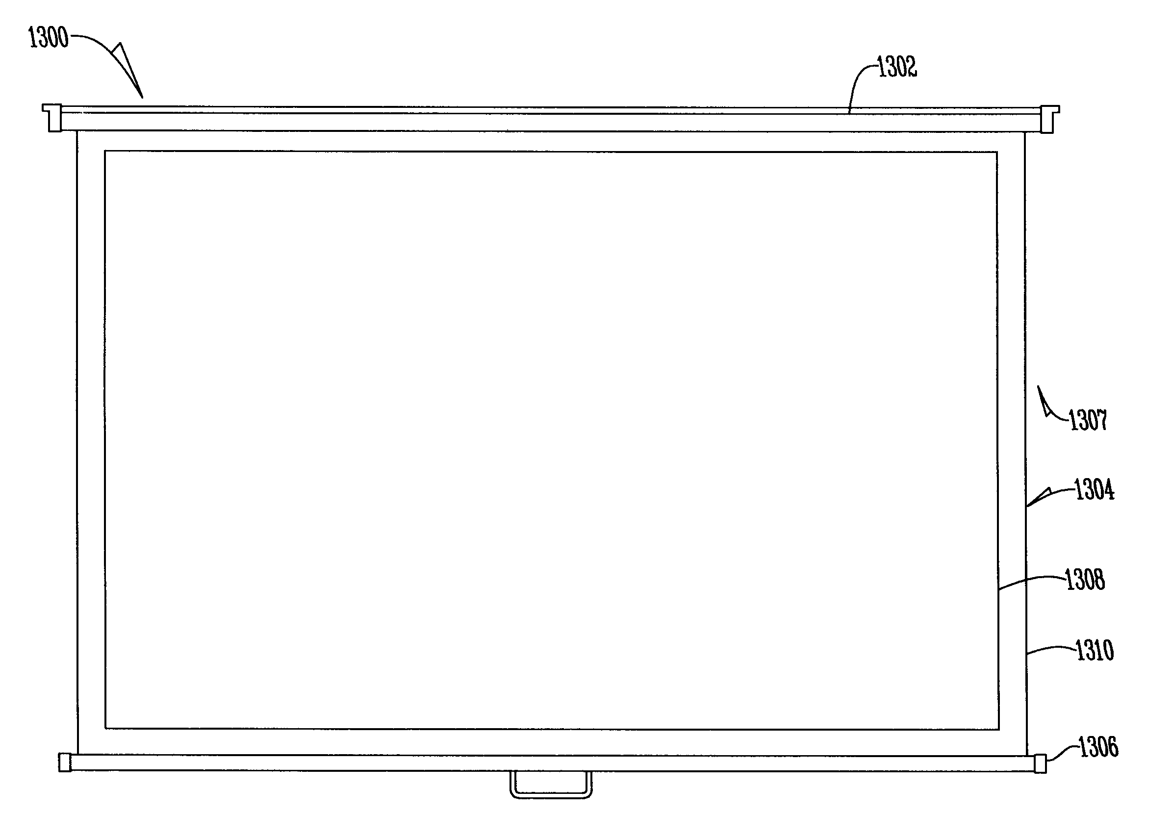
The invention advantageously provides a deployable screen system that includes a roller tube, a motor / controller unit and a power supply unit. The motor / controller unit is disposed within the roller tube, and includes a bearing, rotatably coupled to a support shaft, and a DC gear motor. The output shaft of the DC gear motor is coupled to the support shaft such that the output shaft and the support shaft do not rotate when the support shaft is attached to the mounting bracket. The deployable screen system is operable by tugging, manual movement and wireless control. The DC gear motor is underpowered by a plurality of batteries positioned within the roller tube. In this way a novel, useful and nonobvious deployable screen system is presented.
Description
CROSS REFERENCE TO A RELATED APPLICATION[0001]This application is a continuation-in-part of U.S. Ser. No. 14 / 018,823 filed Sep. 5, 2013 which is a continuation of U.S. Ser. No. 13 / 653,451 filed Oct. 17, 2012, now U.S. Pat. No. 8,575,872 issued Nov. 5, 2013, which is a continuation-in-part of U.S. Ser. No. 12 / 711,193 filed Feb. 23, 2010, now U.S. Pat. No. 8,368,328 issued Feb. 5, 2013.FIELD OF THE INVENTION[0002]This invention relates to a motorized screen. More specifically, this invention relates to a high-efficiency roller screen and method of operation.BACKGROUND OF THE INVENTION[0003]Screens for projectors, such as projection televisions, are old and well known in the art. In their simplest form, these screens were formed of a simple panel of fabric, such as a piece of white material (“screen material”), hung from a ceiling or wall. While effective, these installations were somewhat permanent and in some applications it was desirable to have these screens be less-permanent, or r...
Claims
Application Information
Patent Timeline
Application Date:The date an application was filed.
Publication Date:The date a patent or application was officially published.
First Publication Date:The earliest publication date of a patent with the same application number.
Issue Date:Publication date of the patent grant document.
PCT Entry Date:The Entry date of PCT National Phase.
Estimated Expiry Date:The statutory expiry date of a patent right according to the Patent Law, and it is the longest term of protection that the patent right can achieve without the termination of the patent right due to other reasons(Term extension factor has been taken into account ).
Invalid Date:Actual expiry date is based on effective date or publication date of legal transaction data of invalid patent.

