Supercharge Your Innovation With Domain-Expert AI Agents!

Centrifugal engagement and disengagement drive systems

a technology of centrifugal engagement and drive system, which is applied in the direction of mechanical actuated clutches, clutches, actuators, etc., can solve the problems of the clutch device being connected to the output shaft and becoming jammed

Inactive Publication Date: 2015-10-13
HONEYWELL INT INC
View PDF8 Cites 3 Cited by
  • Summary
  • Abstract
  • Description
  • Claims
  • Application Information

AI Technical Summary

Problems solved by technology

However, in some cases, the rotation of the input drive shaft may overwhelm the output drive shaft potentially damaging the elements (for example, the wheel assembly) connected to the output shaft.
In other instances, the clutch device may become jammed staying connected to the output shaft after a command to disengage has been sent.

Method used


Image

  • Centrifugal engagement and disengagement drive systems
  • Centrifugal engagement and disengagement drive systems
  • Centrifugal engagement and disengagement drive systems

Examples


Embodiment Construction

[0012]The following detailed description is of the best currently contemplated modes of carrying out the invention. The description is not to be taken in a limiting sense, but is made merely for the purpose of illustrating the general principles of the invention, since the scope of the invention is best defined by the appended claims.

[0013]Various inventive features are described below that can each be used independently of one another or in combination with other features. However, any single inventive feature may not address any of the problems discussed above or may only address one of the problems discussed above. Further, one or more of the problems discussed above may not be fully addressed by any of the features described below.

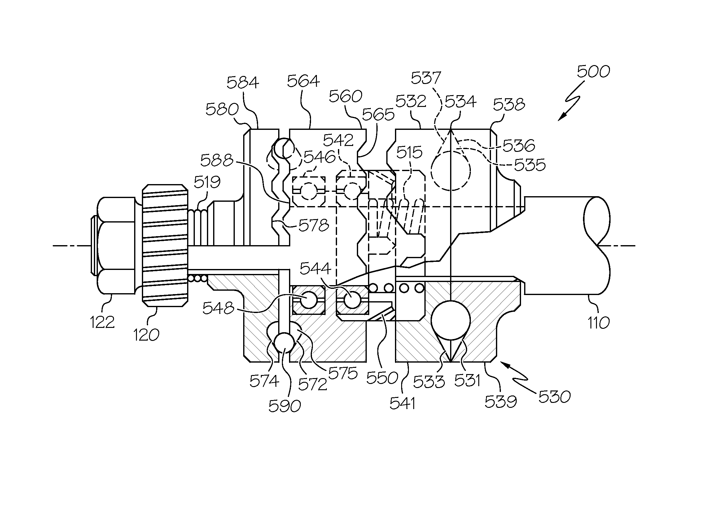
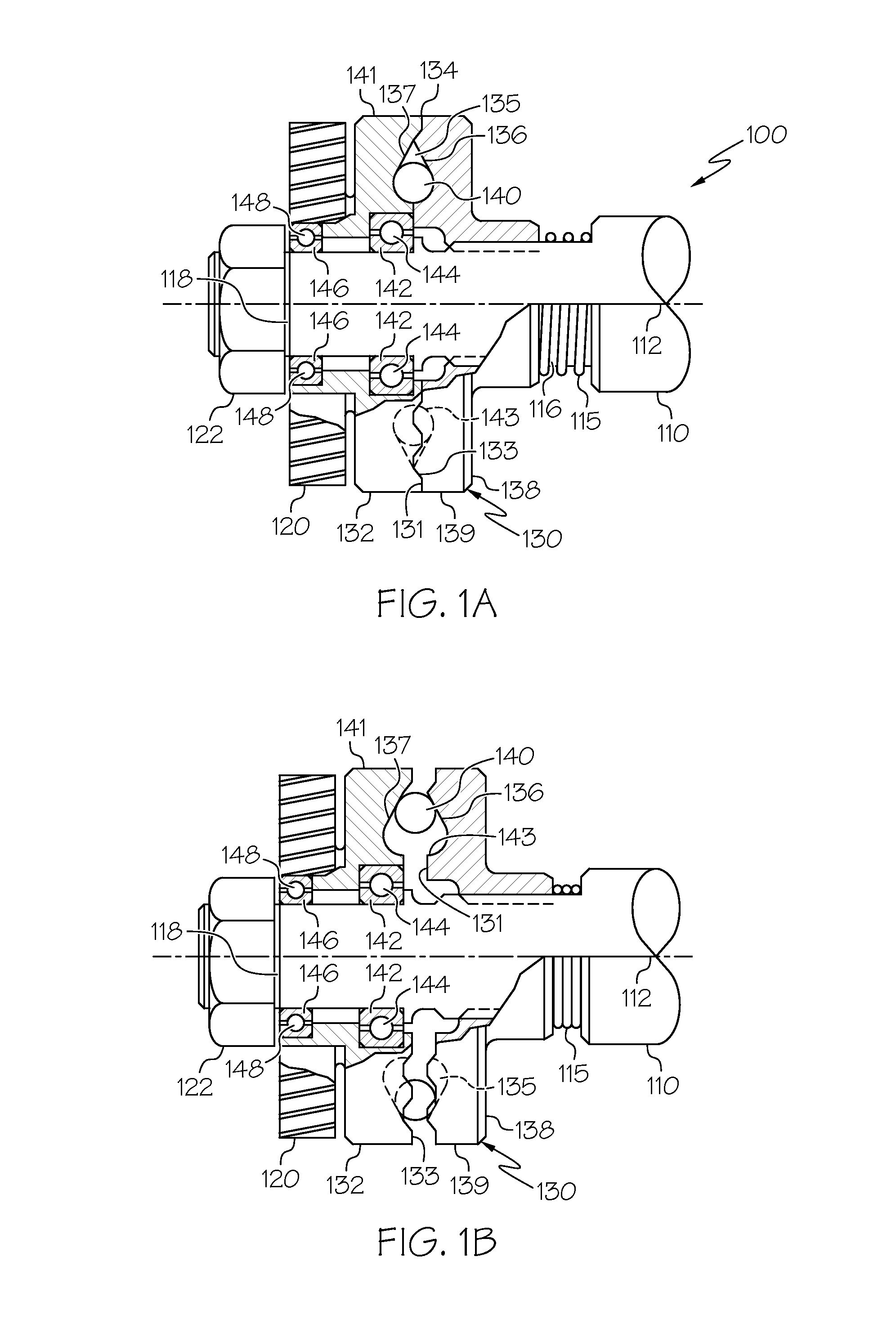
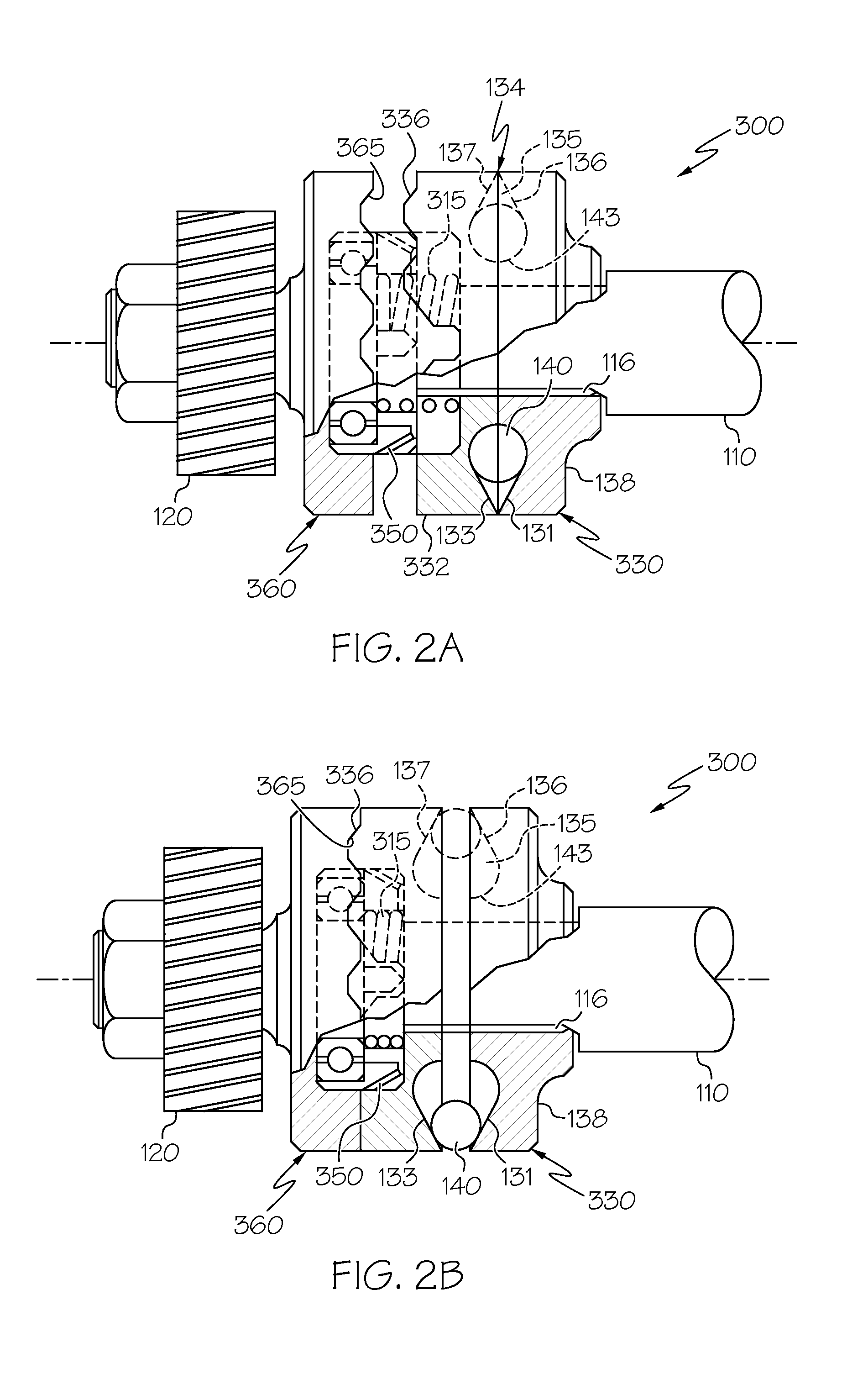
[0014]The present invention generally provides a clutch system that may be beneficial to, for example, taxi systems in aircraft. The embodiments disclosed may be useful in engagement and disengagement of electric motors to aircraft wheels. In some exem...


PUM


Abstract

A drive system may provide centrifugally driven clutch members into engagement and disengagement using weights between an interface of the clutch members. The weights maybe disposed in races between the clutch members. The weights may move centrifugally within the races pushing the clutch members apart during rotation of an input drive shaft. In some embodiments, two clutch members may provide the engagement and disengagement of the input drive shaft power to a drive output member and a third clutch member may be configured to engage the two clutch members during drive engagement. The third clutch member may be configured to disengage from the two clutch members as a failsafe during, for example, an overspeed condition or a jammed clutch interface.

Description

BACKGROUND OF THE INVENTION[0001]The present invention generally relates to drive systems and more particularly, centrifugal engagement and disengagement drive systems.[0002]In some aircraft, the wheels may be electrically driven by the motor during taxiing (sometimes referred to as E-taxi systems). Engagement and disengagement of the wheels to move the aircraft may require a clutch device to transfer drive power from the motor to the wheels. In some systems, the clutch device may be engaged by a direct command from the pilot. It is known to use, for example, push / pull type clutches to engage the input shaft with the output shaft. However, in some cases, the rotation of the input drive shaft may overwhelm the output drive shaft potentially damaging the elements (for example, the wheel assembly) connected to the output shaft. In other instances, the clutch device may become jammed staying connected to the output shaft after a command to disengage has been sent.[0003]As can be seen, t...

Claims


Application Information

Patent Timeline
Patent Type & Authority Patents(United States)
IPC IPC(8): F16D43/06F16D43/30F16D129/04
CPCF16D43/06F16D43/30F16D2129/043F16D23/04
Inventor MITCHELL, ROBERT K.STEVES, ALLAN D.KNORR, JAMES
Owner HONEYWELL INT INC
Features
  • R&D
  • Intellectual Property
  • Life Sciences
  • Materials
  • Tech Scout
  • Unparalleled Data Quality
  • Higher Quality Content
  • 60% Fewer Hallucinations
Learn More