Snowmobile

a technology for snowmobiles and motors, applied in the field of snowmobiles, can solve the problems of large track angle, and achieve the effect of less maneuverability, less turning torque, and hindering the forward movement of the vehicl

Active Publication Date: 2015-10-20
BOMBARDIER RECREATIONAL PROD INC
View PDF27 Cites 0 Cited by
  • Summary
  • Abstract
  • Description
  • Claims
  • Application Information

AI Technical Summary

Benefits of technology

[0011]A large distance between the attachment points of the front suspensions to the skis and the front drive axle has the effect of increasing the moment the ski creates to turn the snowmobile. Because the drive track in an off-trail snowmobile is often longer and wider, the friction created by the drive track induces less maneuverability. As a result, a longer distance applies more turning torque and helps overcome the friction between the drive track and the snow on the ground. In addition, such a longer snowmobile would be inconvenient to package and to maneuver. Therefore, a range of distances between the attachment points of the skis to the front suspensions and the front drive axle was identified which addresses the above.
[0012]Finally, the choice of front suspensions also has an effect on the deep snow capabilities of the snowmobile. A double A-arm type of suspension has more components that can drag in the snow and thus hinders its forward movement. However, telescopic suspension struts do not drag in the snow since there are always in the path created by the skis.
[0013]Although any one of the above may provide improved off-trail performance, it was found that the right combinations of an average hull angle, a track angle, and a distance from the attachment points to the front drive axle within the identified ranges, together with the choice of telescopic suspension struts were found to provide optimum performance for an off-trail snowmobile.

Problems solved by technology

When the average hull angle is too high, the bottom surface of the hull creates a wall with the oncoming snow and tends to push the snow as a plow would do.
However, when the average hull angle is too low, the engine and the front drive axle have to be raised to ensure enough ground clearance.
In addition to cause the snowmobile to be unstable, a high ground clearance induces a large track angle, which is problematic as discussed below.

Method used


Image

  • Snowmobile
  • Snowmobile
  • Snowmobile

Examples


Embodiment Construction

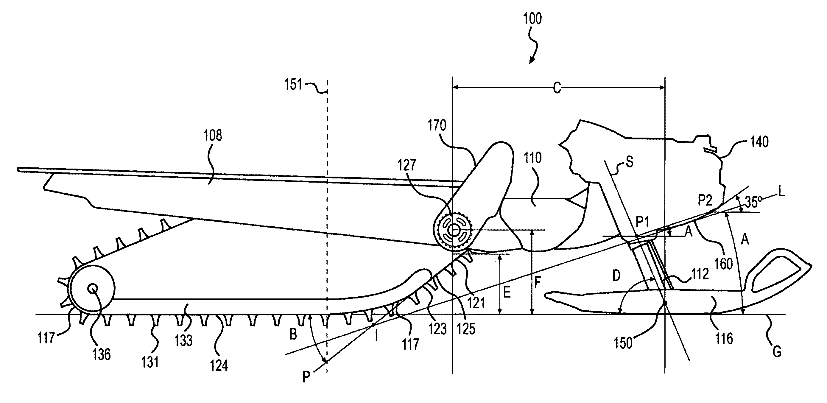
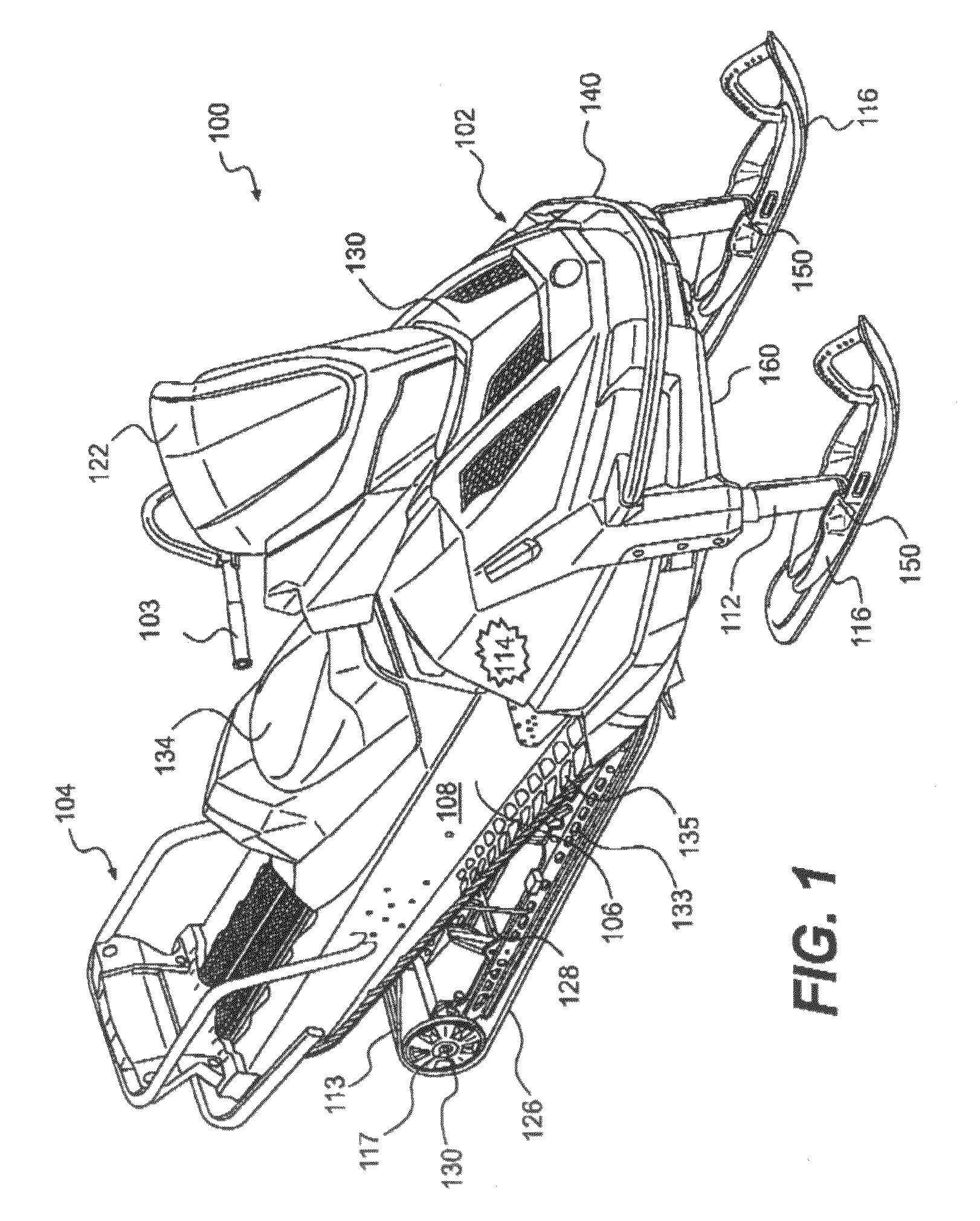
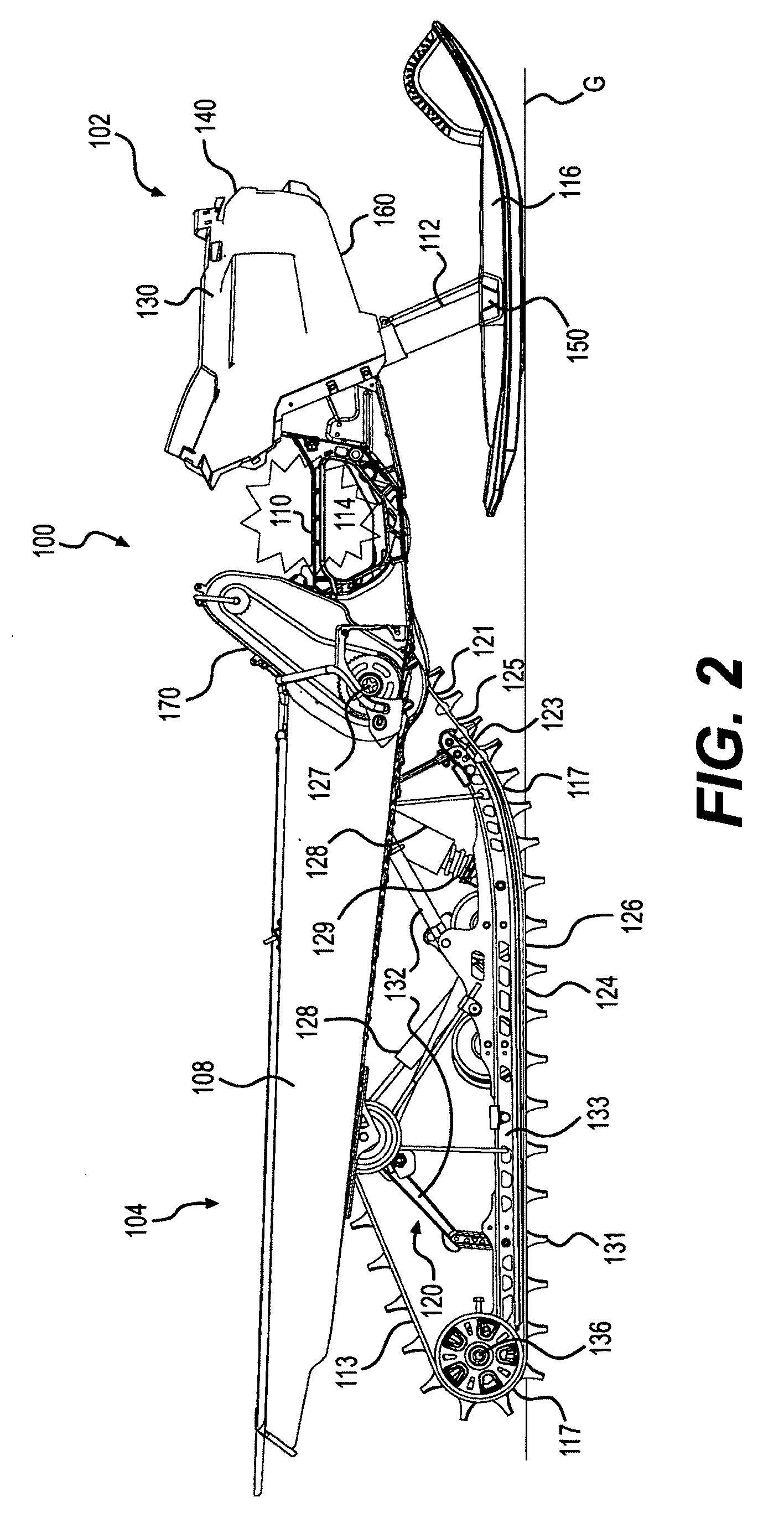
[0044]As shown in FIG. 1, a snowmobile 100 according to the present invention includes a front portion 102 and a rear portion 104 which are defined consistently with a forward travel direction of the vehicle. As best seen in FIG. 2, the snowmobile 100 includes a frame (also known as a chassis) 106 which includes a rear tunnel 108, an engine cradle 110 (seen in FIG. 2) attached to a forward portion of the tunnel 108 and extending forwardly therefrom, and a left and right telescopic suspension struts 112 disposed forwardly of the engine cradle 110 and attached thereto in a manner that will be discussed below in further detail. The tunnel 108 generally consists of one or more pieces of a suitable sheet metal such as aluminium or steel stamped into an inverted U-shape. An engine 114 (shown schematically) is disposed on the engine cradle 110, which forms part of an engine compartment. The engine 114 is oriented such that the crankshaft (not shown) is transverse to the normal direction of...


PUM


Abstract

A snowmobile (100) has a frame (106) comprising a tunnel (108) and an engine cradle (110) containing an engine (114). A drive track (126) is operatively connected to the tunnel. A front drive axle (127) connected to the engine engages the drive track. A front (102) of the snowmobile comprises a hull connected to the frame and to front telescopic suspension struts (112). The snowmobile also comprises front skis (116) connected at attachment points (150) to the front telescopic suspension struts. The drive track has a front portion (125) defining a track angle (B) between 20 and 40 degrees from horizontal. A horizontal distance (C) between the attachment points and the front drive axle is between 600 mm and 900 mm. The hull has a bottom surface (160) wherein at least a portion has an average hull angle (A) between 10 and 30 degrees from horizontal.

Description

FIELD OF THE INVENTION[0001]The present invention relates to snowmobiles designed for off-trail riding.BACKGROUND OF THE INVENTION[0002]Off-trail snowmobiles must be able to advance through deep snow, whether it be soft powder or heavy damp snow. In either case, an off-trail snowmobile must be able to propel itself onto the snow rather than through the snow. Off-trail snowmobiling is done most of the time at relatively low speeds compared to the maximum speed the snowmobile is capable of, or compared to cruising speeds on groomed trails. Because of this low speed, the snowmobile cannot rely on its own momentum to get through the deep snow but rather on its floatation characteristics to push the snowmobile on top of the snow and reduce the drag between the snow and the snowmobile body components.[0003]Several structural parts of a snowmobile are playing a role in maintaining the snowmobile on top of the snow. A drive track and skis provide the majority of the floatation. In an off-tr...

Claims


Application Information

Patent Timeline
Patent Type & Authority Patents(United States)
IPC IPC(8): B62M27/02
CPCB62M27/02B62M2027/026B62M2027/027B62M2027/028
Inventor MALTAIS, HUGUES
Owner BOMBARDIER RECREATIONAL PROD INC
Why Eureka
Try Eureka