Robotic cleaning head

a cleaning head and robot technology, applied in the field of robotic cleaning heads, can solve problems such as adversely affecting the steering accuracy, and achieve the effect of less sensitive manoeuvr

Inactive Publication Date: 2012-03-20
KONINK PHILIPS ELECTRONICS NV
View PDF7 Cites 31 Cited by
  • Summary
  • Abstract
  • Description
  • Claims
  • Application Information

AI Technical Summary

Benefits of technology

[0004]It is an object of the invention to provide a cleaning head of which the maneuverability is less sensitive to forces exerted upon it by the hose to which it is connected.
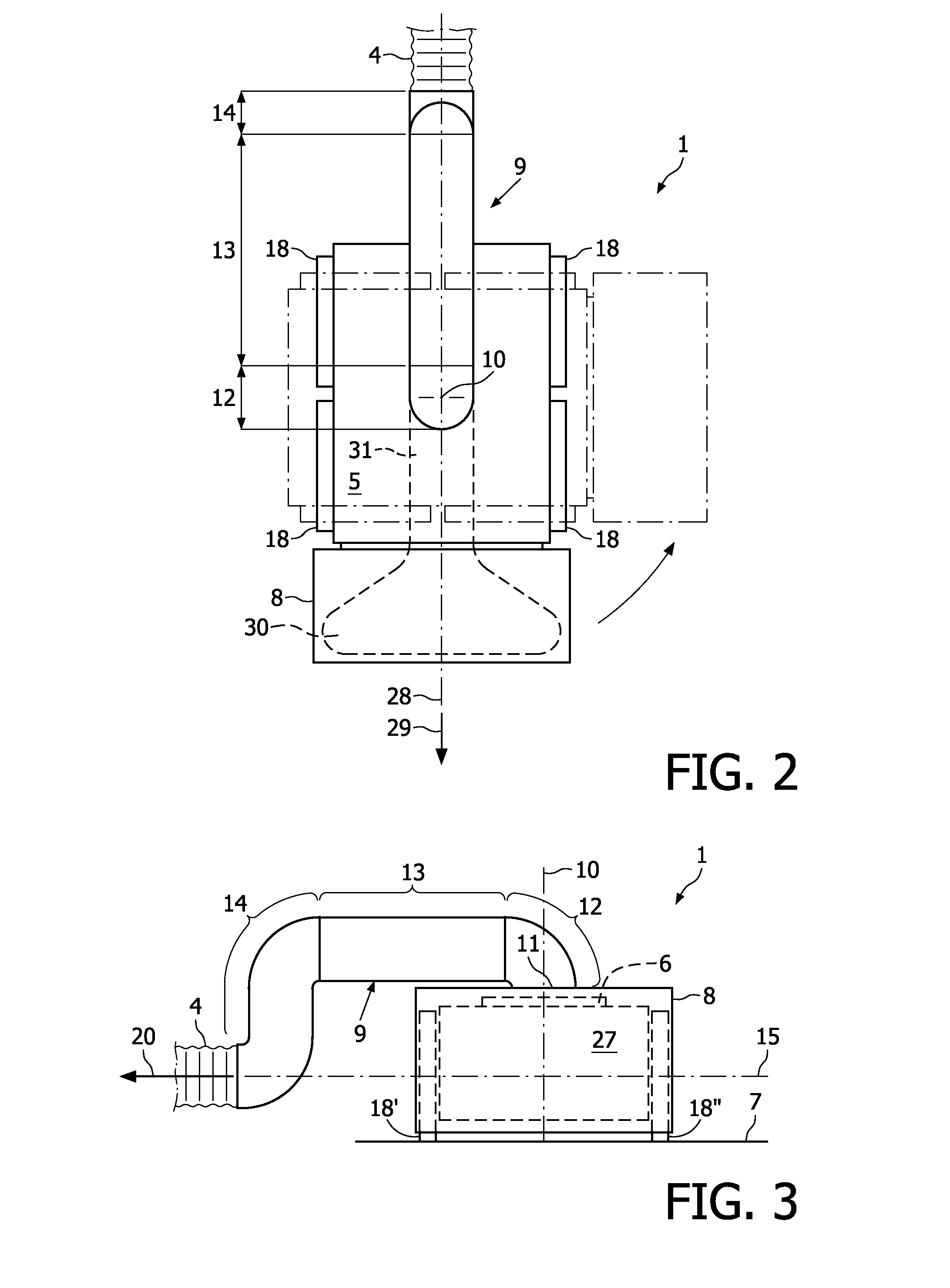
[0006]Because the conduit is suspended and shaped such that, in operating condition, a line of action of a tension force exerted by the hose assembly onto the chassis via the conduit to which the hose assembly is connected, extends below a downstream end of the elbow section, the tilting moment resulting from the force exerted upon the cleaning head by the hose and the friction forces between the floor and the cleaning head is relatively small. Accordingly, the tilting moment exerted on the cleaning head at given forces exerted by the hose is substantially reduced. Therefore, there is less reduction of contact pressure between the drive system and the floor on one side of the drive system. Such a reduction of the contact pressure between the drive system and the floor on one side of the drive system allows the drive system to slip more easily over the floor on that side, thereby adversely affecting the steering accuracy.
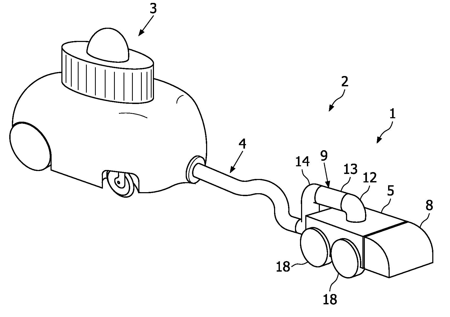
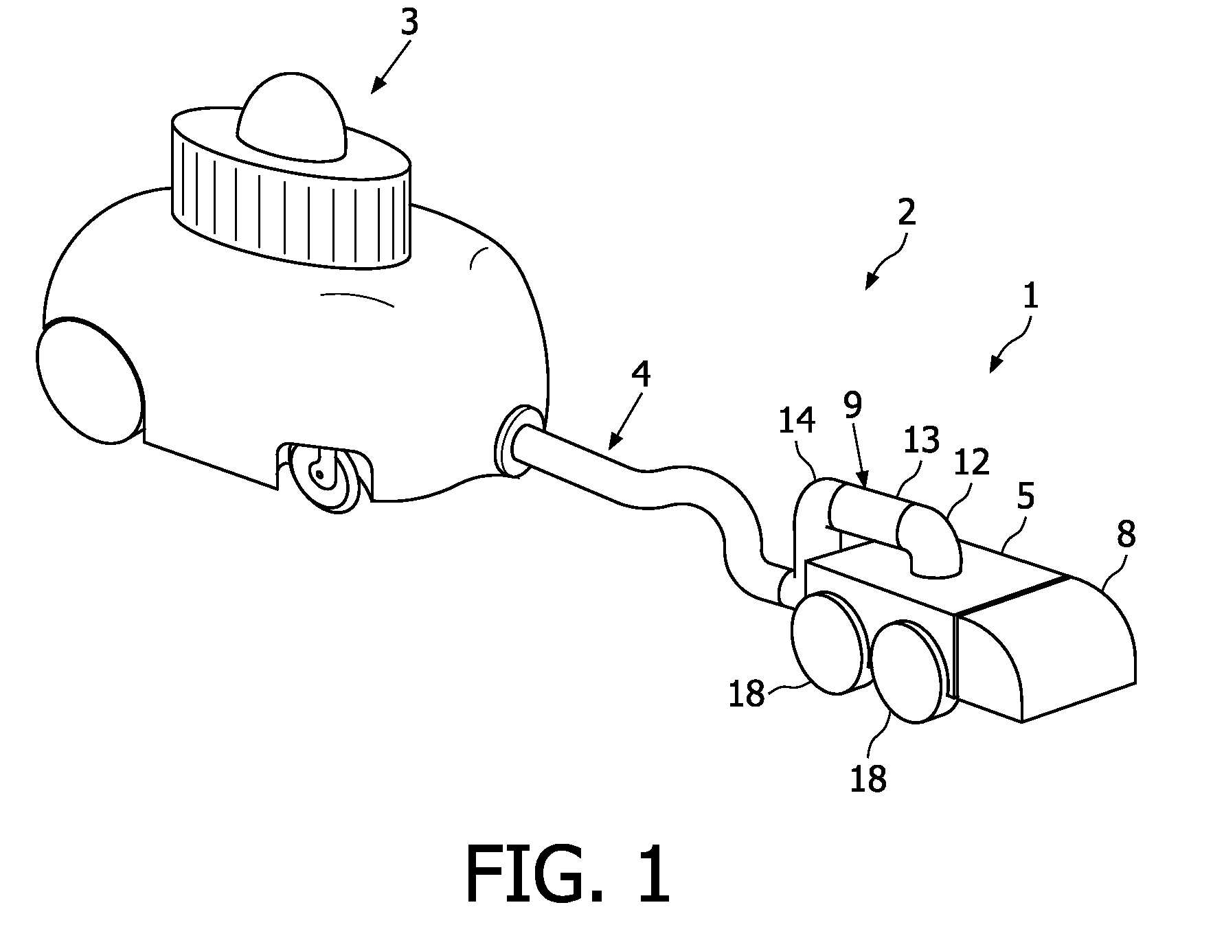
[0007]The conduit may include a boom section extending from the elbow section radially relative to the pivot axis and an outlet end section downstream of the boom section and at least partially extending horizontally outside of the chassis and the drive system and downwardly from the boom section, such that, when in operating condition, a lowermost portion of the outlet end portion is at a level below an uppermost portion of at least the chassis, the drive system or the nozzle. By means of these features, the lowering of the line of action along which the tension forces exerted by the hose assembly are transferred onto the chassis is achieved in a constructionally simple manner. Moreover, because of the lowered position of the outlet end of the conduit to which the hose assembly is to be connected, when in operation, only a relatively short portion of the hose assembly extends from the floor to the conduit, so that relatively little weight of the hose assembly is carried by the conduit. Accordingly, the contribution of the weight of the hose assembly portion carried by the conduit to any tilting moment causing unloading of the wheels on the side of the cleaning head facing away from the conduit is kept relatively small.
[0010]The swivel axis may be a virtual swivel axis defined by a linkage linking the elbow section to the chassis, such as a linkage including at least two links of at least one four bar linkage including the elbow section and the chassis. If, moreover, for at least one position of the linkage, the swivel axis extends below the chassis, a particularly effective reduction or even elimination of the tilting moment is achieved, because the line of action of the frictional reaction forces between the floor and the cleaning head extends along the floor, i.e. very closely along or even intersecting the swivel axis that determines the line of action along which a tension force exerted by the hose assembly is transferred onto the cleaning head. By, moreover, providing a support member under the outlet end portion of the conduit, for supporting the conduit relative to the floor surface, the swivability in operation of the conduit relative to the chassis may be limited. This is advantageous for keeping the conduit from reaching a limit of its range of swivability about the swivel axis, thereby preventing the transfer of any significant moment about the swivel axis from the conduit to the chassis.
[0013]If the inlet end of the conduit is facing upwardly and the pivotable conduit connects from underneath to an air duct portion communicating with the nozzle, the pivotable conduit can connect pivotably to the non pivotable air duct communicating with the nozzle at a low level so as to keep moments in a vertical plane transferred through the pivotable connection low. Moreover, the elbow section can be connected swivably to the chassis in a simple manner by means of a linkage positioned between the conduit and the chassis.

Problems solved by technology

Such a reduction of the contact pressure between the drive system and the floor on one side of the drive system allows the drive system to slip more easily over the floor on that side, thereby adversely affecting the steering accuracy.

Method used


Image

  • Robotic cleaning head
  • Robotic cleaning head
  • Robotic cleaning head

Examples


Embodiment Construction

[0019]In FIG. 1, an autonomous vacuum cleaning system 2 composed of a canister unit 3, a robotic cleaning head 1 and a hose assembly 4 interconnecting the canister unit 3 and the robotic cleaning head 1 is shown.

[0020]According to the present example, the canister unit 3 is self-propelled and self-steering and includes a drive system, a canister, a power supply and an electric fan for generating suction power. The drive system of the canister unit 3 has two driven wheels located at the back corners (only one is visible in the figure) and two castors located near the hose connection at the front of the canister unit (only one is visible in the figure).

[0021]The cleaning head 1 (shown in more detail in FIGS. 2 and 3) is also self-propelled and self-steering by means of a drive system including a control system 6, a drive assembly 27 and wheels 18. The vacuum hose assembly 4 communicates with a cleaning nozzle 8 of the cleaning head 1 so that the vacuum generated by the canister unit i...


PUM


Abstract

A robotic cleaning head (1; 101) for use as part of an autonomous vacuum cleaning system (2) including a canister unit (3) and a hose assembly (4; 104) connecting the cleaning head (1; 101) to the canister unit (3). The cleaning head (3) has a chassis (5; 105), a drive system (6; 18; 27), a vacuum cleaning nozzle (8; 108) and a conduit (9; 109). The conduit (9; 109) communicates with an air passage bound by the cleaning nozzle (8; 108). It is suspended pivotable about a pivot axis (10; 110) and includes an inlet (11; 111) provided on top of said chassis (5; 105), and an elbow section (12; 112) downstream of the inlet (11; 111), and the conduit (9; 109) is suspended and shaped such that a line of action (15; 115) of a tension force (20; 120) exerted by the hose assembly (4; 104) onto the chassis (5; 105), via the conduit (9; 109) to which the hose assembly (4; 104) is connected, extends spaced below a downstream end of the elbow section (12; 112).

Description

FIELD OF THE INVENTION[0001]The invention relates to a robotic cleaning head for use as part of an autonomous vacuum cleaning system further including a canister unit and a hose assembly connecting the cleaning head to the canister unit.BACKGROUND OF THE INVENTION[0002]Such a robotic cleaning head is disclosed in European patent application 1 360 922. The canister unit holds a fan, a motor for driving the fan, dust filters and a dust collection chamber. Thus, the cleaning head can have relatively small dimensions, which is advantageous for agility and for reaching encumbered areas, for example, under furniture and in corners. For the maneuverability of the cleaning head, it is advantageous that the hose connects to a conduit of the cleaning head which is pivotable about a pivot axis and that the conduit includes an elbow section downstream of an inlet of the conduit extending coaxially with the pivot axis.[0003]In operation, the hose assembly exerts forces on both the cleaning head ...

Claims


Application Information

Patent Timeline
Patent Type & Authority Patents(United States)
IPC IPC(8): A47L5/00A47L9/00
CPCA47L5/36A47L9/24A47L2201/00
Inventor SPLINTER, ALEXANDER POUL
Owner KONINK PHILIPS ELECTRONICS NV
Why Eureka
Try Eureka