
Hanger for mounting objects of various shapes and sizes

a technology for hanging objects and objects, applied in the field of hanging objects, can solve the problems of difficult assembly of hanging objects, frequent finger pinched by users, and plate may break, and achieve the effect of convenient and safe assembly

Active Publication Date: 2015-10-27
WANIGA TRINA
View PDF5 Cites 0 Cited by
  • Summary
  • Abstract
  • Description
  • Claims
  • Application Information

AI Technical Summary

Benefits of technology

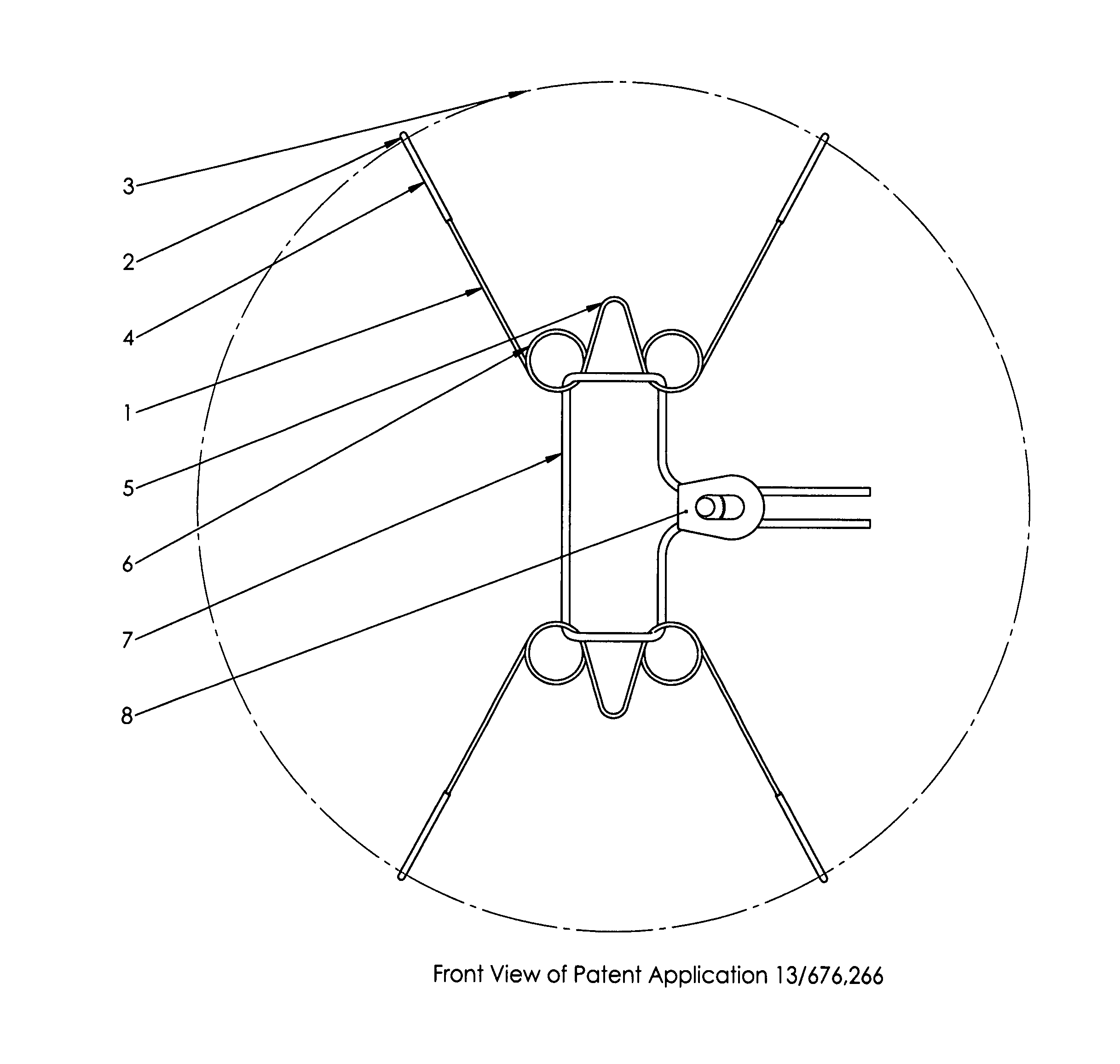
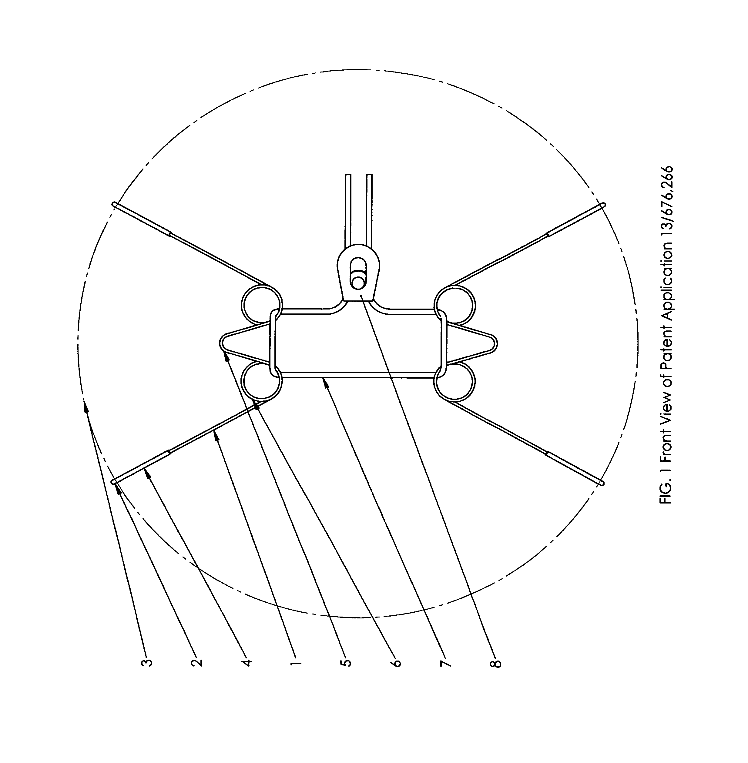
[0002]A hanger according to the invention for mounting an object on a vertical, horizontal or sloping surface comprises a frame consisting of two separate opposing parts, each part being configured to provide at each end a hook or like means for gripping said object, a central section shaped to engage a mounting pin the like projecting from said surface, an aperture on each side of the central section, and means permitting lockable adjustment of a length of cord threaded through all said apertures to link the parts, whereby the spacing between the parts can be varied. Thus the hanger of the present invention can be easily and safely assembled to fit precisely objects of a variety of shapes and sizes without exerting potentially damaging pressure on them.
[0004]Each frame part may be made, conveniently and inexpensively, from a single length of wire of adequate strength fashioned into the shape required. As shown in drawings the shape may be an approximate W, the apertures through which the cord is passed being formed by looping the wire. For hanging heavy objects, the two loops of each frame part may be braced so as to maintain them a fixed distance apart under stress. Twenty-two (22) (0.06″) gauge stainless steel wire and Three Thirty-second ( 3 / 32) inch braided nylon cord have been found to work well.
[0006]Objects such as plates, bowls, platters and trays having a rim can be securely mounted by engaging the hooks of the frame parts with their rims. Pictures may be mounted by engaging the edges of their frames with the hooks of the hanger frames or, if desired, by providing rings on the backs of their frames for receiving the hooks. Irregularly shaped objects such as stuffed toys or vases can also be hung without risk of damaging them since the hooks need only exert minimal pressure.

Problems solved by technology

These hangers are difficult to assemble.
If the plates are initially not securely gripped, the springs may retract with force and the users frequently suffer pinched fingers and the plate may be broken.
The Inventor's Design Registration U.S. D534,004 illustrates a hanger in which a bungee cord has been substituted for the springs, which makes it a little easier to install, but the size of an object that can be mounted using any hanger of the prior art is limited by the maximum possible extension of the springs or bungee cord.
In addition, when the springs or the bungee cord are extended to or near to their limits, significant pressure may be exerted on and may cause damage to the object being hung.

Method used


Image

  • Hanger for mounting objects of various shapes and sizes
  • Hanger for mounting objects of various shapes and sizes
  • Hanger for mounting objects of various shapes and sizes

Examples


Embodiment Construction

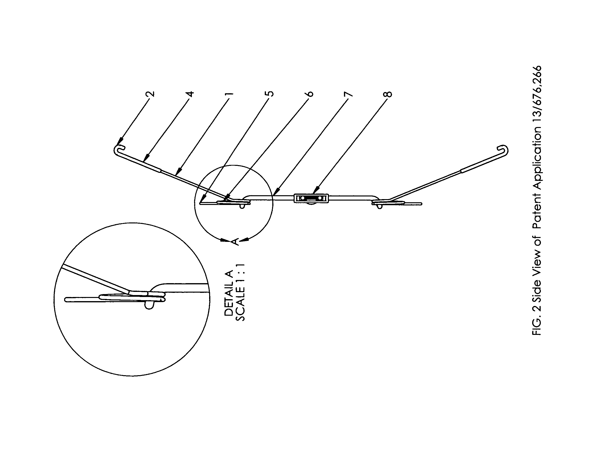
[0009]As shown in FIGS. 1 to 3, each frame part is fashioned from a single piece of Wire1, the ends of which are bent to form hooks 2 for gripping the rim 3 of a plate. The ends of the wire, including the hooks, are provided with a plastic coating 4. On each side of the central section 5, the wire is formed into a loop 6 through which a cord 7 is passed. The ends of the cord 7 are threaded into a reversible locking device or fastener 8. With reference to Figs 4 and 5 of the drawings, the fastener comprises a housing 9, one end 11 of with is wider than the other end 12, and a clamping roller 13 located and movable longitudinally within the housing. The two ends of the cord 7 can be passed freely through the housing, one on each side of the roller when it is located at the wide end 11 of the housing, but when it is moved to the narrow end 12 of the housing the ends of the cord 7 are clamped against the inner wall 10 of the housing and locked in place. Thus the length of the cord linki...


PUM


Abstract

The invention relates to a hanger for mounting objects of various shapes and sizes on vertical, sloping or horizontal surfaces. The hanger comprises a frame formed by two opposing parts adapted to grip the object, and linked together by an adjustable length of cord so that the frame can be made to fit precisely the object to be hung. The disadvantages of the prior art hangers that rely on springs to provide for the adjustment needed for them to fit a range of sizes will be overcome.

Description

BACKGROUND OF THE INVENTION[0001]This invention relates to a hanger for securely mounting objects of various shapes and sizes on vertical, horizontal or sloping surfaces. Hangers currently marketed for mounting objects, primarily circular plates on walls, rely on the use of springs to provide for the adjustment needed for them to fit a fixed diameter range of plate sizes. These hangers are difficult to assemble. If the plates are initially not securely gripped, the springs may retract with force and the users frequently suffer pinched fingers and the plate may be broken. The Inventor's Design Registration U.S. D534,004 illustrates a hanger in which a bungee cord has been substituted for the springs, which makes it a little easier to install, but the size of an object that can be mounted using any hanger of the prior art is limited by the maximum possible extension of the springs or bungee cord. In addition, when the springs or the bungee cord are extended to or near to their limits,...

Claims


Application Information

Patent Timeline
Patent Type & Authority Patents(United States)
IPC IPC(8): A47F7/14A47G1/16F16M13/02A47F5/08
CPCF16M13/022A47F5/08F16M13/02
Inventor WANIGA, TRINA
Owner WANIGA TRINA
Learn More