Contact device mechanically mountable and electrically connectable on a printed circuit board by a fastening portion for receipt of an external plug element

a technology of electrical connection and contact device, which is applied in the direction of electrically conductive connection, coupling device connection, electrical apparatus, etc., can solve the problems of inability to precisely guide the insertion of contact element or plug element during assembly, and the deformation of contact element cannot be excluded, so as to achieve convenient and safe assembly, prevent oscillation of circuit board, and facilitate insertion and equally safe

Inactive Publication Date: 2017-04-25
HKR AUTOMOTIVE GMBH
View PDF6 Cites 0 Cited by
  • Summary
  • Abstract
  • Description
  • Claims
  • Application Information

AI Technical Summary

Benefits of technology

[0008]Therefore, the object underlying the present invention is to design a contact device of the type as mentioned in the beginning so that, on the one hand, even in the case of oscillations of the entire arrangement, safe contact as well as precise and safe mounting is ensured.
[0011]The electrical contact device according to the invention is designed in combination with plural sections (and preferably in one piece) and comprises elastic portions (support element) so that oscillations occurring to a predetermined extent (relative movements) between the contact device and a plug element to be inserted can be compensated. The contact device further includes a basic strength irrespective of the possibility of elastic oscillations so that mounting can be safely and accurately performed. Hence easy and safe assembly is guaranteed. External plug elements can be inserted easily and equally safely without the risk of the contact device being deformed or bent in an inadmissible or undesired manner (i.e. plastically) in the position after complete mounting, as movements and oscillations are possible to a restricted extent only and safe limitations are ensured by external components in accordance with a mechanical interaction. The limitation of movements of the contact device (or else of parts thereof) is possible by the external limit means to a fixed (predefined) extent only (predefined amplitudes). Internal limitations at the contact device are not required.
[0012]The contact device can be fastened on a base element such as a circuit board, wherein on the other side the contact portion is arranged. Then a plug element (for example in the form of a tab connector) can be inserted. Movements of the plug element relative to the circuit board are compensated to a predetermined extent by the elastically configured contact device. In this way oscillations of the circuit board are efficiently prevented from being transmitted to the plug element or oscillations imparted to the plug element due to its further connections are prevented from being transmitted to the circuit board. Thus the contact device in the afore-described manner very efficiently causes the inserted plug element to be uncoupled in terms of oscillations relative to the circuit board to which the contact device can be mechanically fastened and electrically contacted. At an idle position of the contact device the external limit means are not contacted so that free oscillation is possible to a predetermined extent (with predetermined amplitude).

Problems solved by technology

The contact element known from document DE 10 2004 050 715 B3 has an appropriate elastic portion, wherein there is the problem, however, that when inserting or removing a respective plug means (a plug element) forces are exerted on the entire arrangement of the contact element so that, irrespective of any elasticity of the material, deformation of the contact element cannot be excluded.
Furthermore, due to the elastic characteristics of particular parts of a contact element the contact element or plug elements to be inserted cannot be imperatively guided in a precise manner during assembly.

Method used


Image

  • Contact device mechanically mountable and electrically connectable on a printed circuit board by a fastening portion for receipt of an external plug element
  • Contact device mechanically mountable and electrically connectable on a printed circuit board by a fastening portion for receipt of an external plug element
  • Contact device mechanically mountable and electrically connectable on a printed circuit board by a fastening portion for receipt of an external plug element

Examples


first embodiment

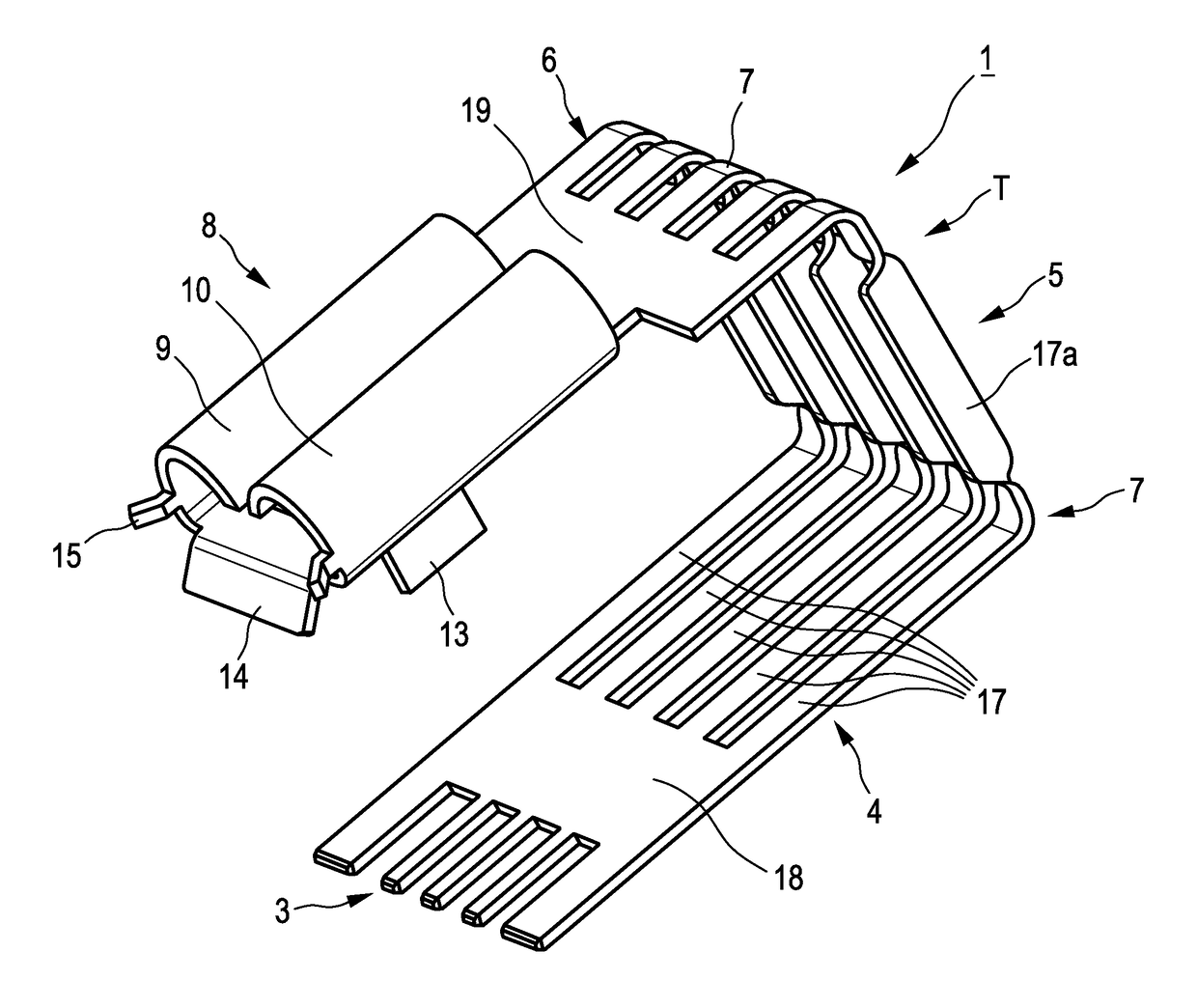
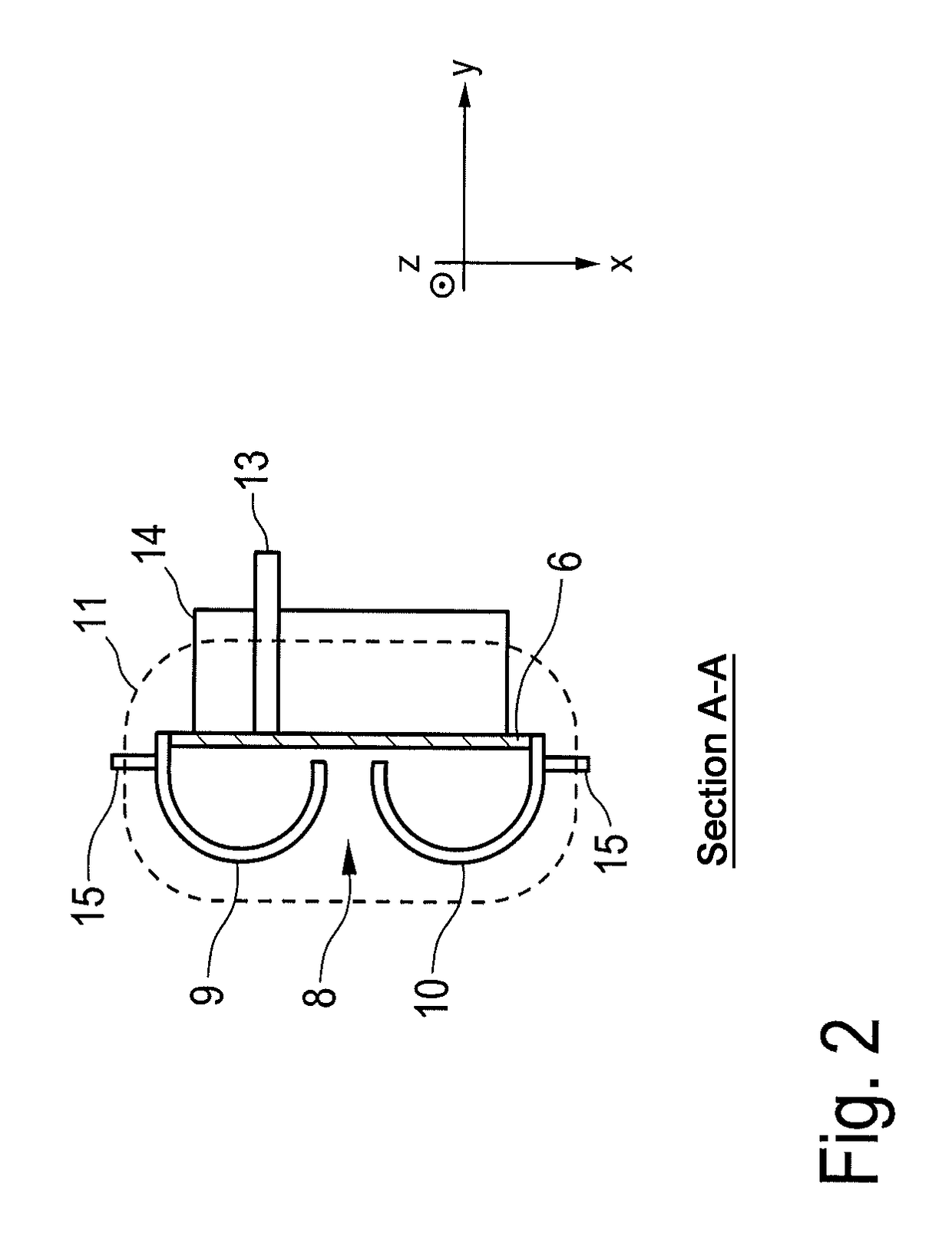
[0030]Hereinafter the structure and the mode of action of the contact device according to the invention in accordance with a first embodiment will be described in detail with reference to FIGS. 1 to 3.

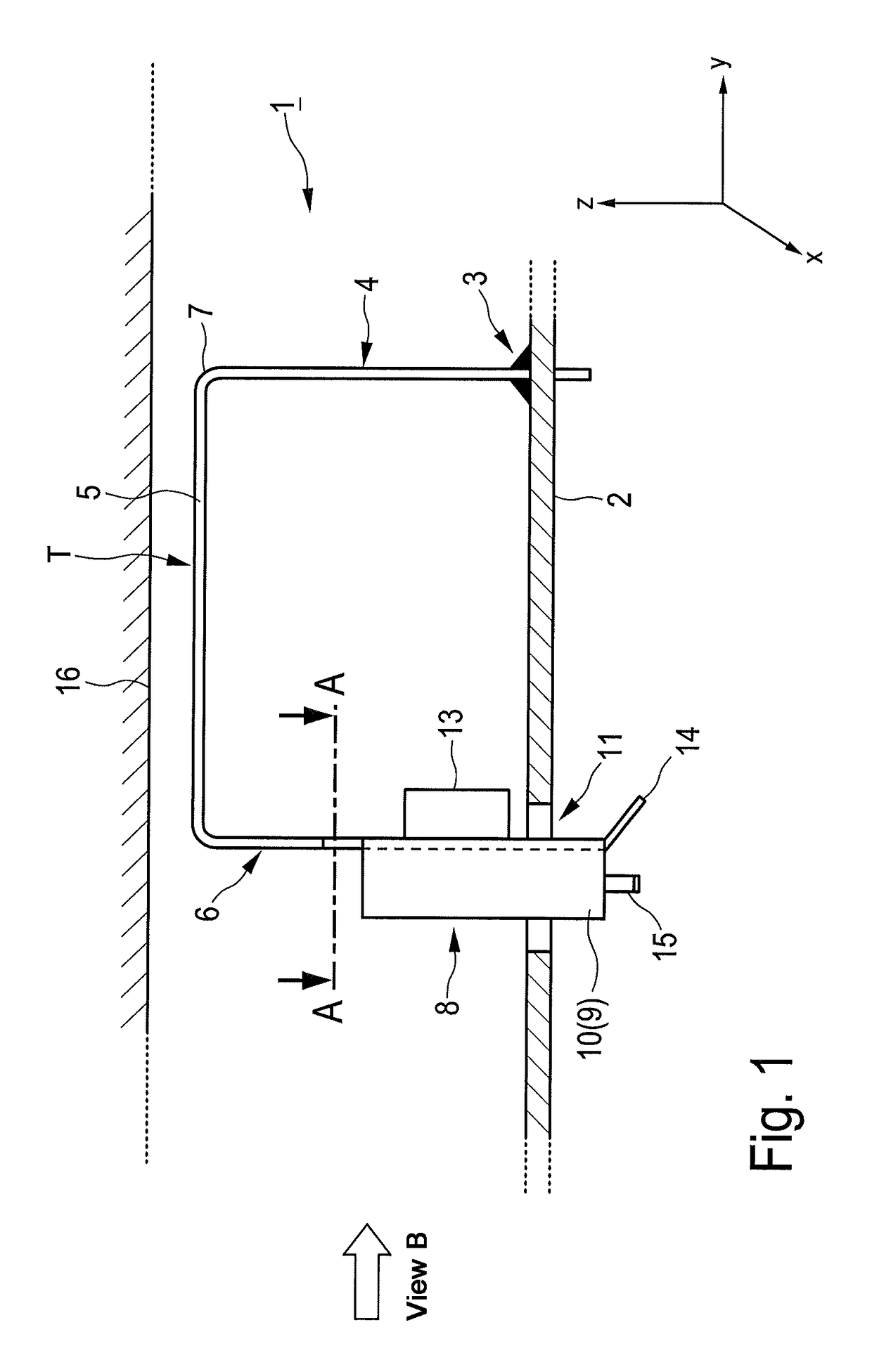
[0031]In the representation according to FIG. 1 the contact device 1 is shown in its entirety, wherein the contact device 1 can be arranged or mounted on a printed circuit board 2. FIG. 1 illustrates the contact device 1 at the position mounted on the circuit board 2 and thus in connection with an application. The fastening of the contact device 1 on the circuit board 2 is performed by a fastening portion 3 of the contact device 1, the contact device 1 being safely fastened on the printed circuit board 2 both in the electrical and mechanical respect. The contact device 1 is thus connectable to the printed circuit board 2 in a mechanically stable manner and in the connected state also includes an electric (galvanic) contact.

[0032]The printed circuit board 2 represents an example of a ba...

second embodiment

[0067]In accordance with the afore-described first embodiment and corresponding to the illustration in FIGS. 3 and 4, for example, the contact device 1 consists of a band material, with appropriate portions of the contact device 1 being curved or bent in a predetermined manner. Preferably, in the contact device 1 related to the first embodiment a strip-shaped sheet metal was used, wherein the basic structure of the contact device 1 was punched out and then the components of the contact device 1 were appropriately bent (for instance at the bending portions 7). The contact device 1 according to the second embodiment is preferably integrally formed of one material in the same way as that of the first embodiment and includes plural portions.

[0068]On the other hand, the contact device 1 according to the second embodiment is made of an originally band-shaped material, as for example and preferably of sheet metal, wherein, according to the representation in FIG. 5 in which the same referen...


PUM


Abstract

A contact device which is adapted to be mechanically mounted and electrically connected on a printed circuit board by a fastening portion and serves for receiving an external plug element. The contact device comprises a contact portion for inserting the external plug element for forming an electrical contact, an elastic support element for movably supporting the contact portion and for providing a possibility of movement in all spatial directions, wherein the support element includes a fastening part by which the contact device is fastened on the printed circuit board, a contact part for directly supporting the contact portion and a center part for connecting the fastening part and the contact part, the fastening part and the contact part bent relative to the center part, and of movement of the contact part and center part are limited by predetermined distances from adjacent external limiting means in the fastened state.

Description

CROSS REFERENCE TO RELATED APPLICATION[0001]This application claims priority under 35 USC §119 to German Patent Application No. 202014105937.7 filed on Dec. 9, 2014, which application is hereby incorporated by reference in its entirety.TECHNICAL FIELD[0002]The present invention relates to a contact device, and especially to a contact device adapted to be mounted on a printed circuit board for receiving an external plug means.BACKGROUND OF THE INVENTION[0003]A contact device or, resp., connecting means is known, for example, from document DE 203 05 313 U1, the connecting means being designed for providing a detachable plug-in connection between power rails. The known connecting means includes a specific contact spring having opposing contact tongues so that a contact zone is formed between the contact tongues. The contact tongues are surrounded at their sides facing away from each other by free ends of a super-spring and are appropriately resiliently forced toward each other. Between...

Claims


Application Information

Patent Timeline
Patent Type & Authority Patents(United States)
IPC IPC(8): H01R12/00H01R12/91H01R11/01H01R13/11H01R12/57H01R12/58H01R13/115H01R12/71H05K1/00H01R11/03
CPCH01R11/01H01R11/03H01R12/57H01R12/58H01R12/718H01R12/91H01R13/11H01R13/115
Inventor BRAND, MATTHIAS
Owner HKR AUTOMOTIVE GMBH
Why Eureka
Try Eureka