Incontinence collection device and related methods

a collection device and incontinence technology, applied in the field of external incontinence collection devices, can solve the problems of male urinary incontinence, current devices, subject users to adverse health issues, etc., and achieve the effects of facilitating the collapse of the receptacle, preventing backflow of urine, and flat arrangemen

Active Publication Date: 2018-04-12
PIERSON KENNETH
View PDF5 Cites 4 Cited by
  • Summary
  • Abstract
  • Description
  • Claims
  • Application Information

AI Technical Summary

Benefits of technology

[0014]Once the urine passes through the collection valve and into the second collection conduit, the urine may pass into a collection receptacle which has a proximal receiving hole in fluid communication with the second collection conduit. The collection receptacle may have a volume sufficient to hold several hours of average urine excretion for an adult male. For example, the collection receptacle may have a maximum volume in a range of about 8 fluid oz. to about a quart. The collection receptacle may be made of a flexible material (e.g., rubber, polyurethane rubber, non-latex material such as nitrile, etc.) to allow the structure to collapse when empty or nearly empty, and to conform to the body as a person wearing the incontinence collection device moves.
[0015]The collection receptacle may include a one-way valve of various designs. In some embodiments, the one-way valve of the collection receptacle may have a similar structure to the one-way valve of the collection valve. In such embodiments, the collection valve may have a double membrane structure, in which the distal ends of the membrane are intermittently bonded together, such that there are intermittent passages between the membranes at or near the distal ends thereof that allow urine to pass downstream from the collection valve into the collection receptacle, but the distal ends of the membrane are prevented from separating and allowing backflow. The passages between distal ends of the dual membranes have a width in the range of about 1 mm to about 20 mm (e.g., about 5 mm to about 15 mm, about 8 mm to about 12 mm, or any value or range of values therein) and the bonding points between the membranes may have widths in the range of about 1 mm to about 20 mm (e.g., about 3 mm to about 18 mm, about 5 mm to about 15 mm, or any value or range of values therein). The width of the bonding points may define the interval between adjacent passages. The one-way valve of the collection receptacle allows urine to pass at low pressure (e.g., seep through the plurality of passages) and flow into the collection receptacle for storage. In some implementations, the dual membrane one-way valve may be connected along a lateral edge to the interior of the collection receptacle in order to aid in keeping the dual membrane structure in a flattened arrangement with the two membranes interfacing with one another in close proximity. The connection of the dual membranes to the interior of the collection receptacle may aid in preventing backflow of urine through the one-way valve to the collection valve.
[0016]In some implementations, the collection receptacle may have a structural features that allow the receptacle to expand with the flow of urine into the collection receptacle at relatively low pressures. For example, the collection receptacle may include billow-like structures or pleats at one or more points along the wall of the collection receptacle. Such billow-like structures or pleats may facilitate the collapse of the receptacle into a flat arrangement, such that the walls of receptacle are roughly parallel to the dual membrane one-way valve therein. The dual membranes of the one-way valve structure may be attached to the collection receptacle at or near the billow-like structure or pleats to further facilitate the collapsed, flat arrangement.
[0017]The collection receptacle may include a drainage conduit at its inferior, distal end for draining fluid from the collection receptacle. The drainage conduit may incorporate a drainage valve at the distal end. In some embodiments, the valve be of various designs that allow the user to open the drainage conduit without needing to have his hands near the distal opening of the drainage conduit. Thus, the drainage conduit may have a sufficient length to allow the drainage valve to be positioned sufficient distance upstream of the distal end of the drainage conduit, such that the collection receptacle can be drained without the user getting urine on his hands or spillage of the urine on the user or other undesirable places (e.g., the floor, user's pants, etc.). The drainage conduit may have a length in a range of about ¼ inch to about five inches (e.g., about a ¼ inch to about two inches, or any value or range of values therein).

Problems solved by technology

Male urinary incontinence is a common medical problem.
Each device either subjects the user to adverse health issues.
More recently a line of products have come out to address the need for a urinary incontinence device for males that attaches externally, however, there are issues with the current devices.
One prominent issue with the current seal is that users incorrectly attach the device resulting in the urine leakage.
However, additional attachment member(s) has not solved the problem.
For users, multiple attachment members may increase the likelihood of creating a poor seal resulting in urine leakage, requiring the reattachment or replacement of the attachment members.
Even with the attachment members optimally positioned and attached, the attachment members may fail due to backflow of urine to the attachment members, which can cause detachment of the incontinence collection device.
In current devices, the collection conduit that collects excreted urine does not adequately prevent backflow.
Due to the fact that urine is warm, upon backflow of urine, the adhesive may dissolve leading to the detachment of the device from the user and urine spillage.
Thus, common acts may lead to the backflow of urine and failure of the adhesive, resulting in detachment of the incontinence device.
Yet another issue with the current external male incontinence device is the drainage valve.
It is difficult for a user to control the flow of urine when initially opening the snap-fit valve cap because the valves are clumsy and awkward and require two hands to operate.
Therefore, the user may spill urine onto their hands or other undesirable places when trying to empty the urine receptacle when opening the snap-fit exit valve.

Method used


Image

  • Incontinence collection device and related methods
  • Incontinence collection device and related methods
  • Incontinence collection device and related methods

Examples


Embodiment Construction

[0054]Reference will now be made in detail to certain embodiments of the invention, examples of which are illustrated in the accompanying drawings. While the invention will be described in reference to these embodiments, it will be understood that they are not intended to limit the invention. To the contrary, the invention is intended to cover alternatives, modifications, and equivalents that are included within the spirit and scope of the invention as defined by the claims. In the following disclosure, specific details are given to provide a thorough understanding of the invention. However, it will be apparent to one skilled in the art that the present invention may be practiced without these specific details.

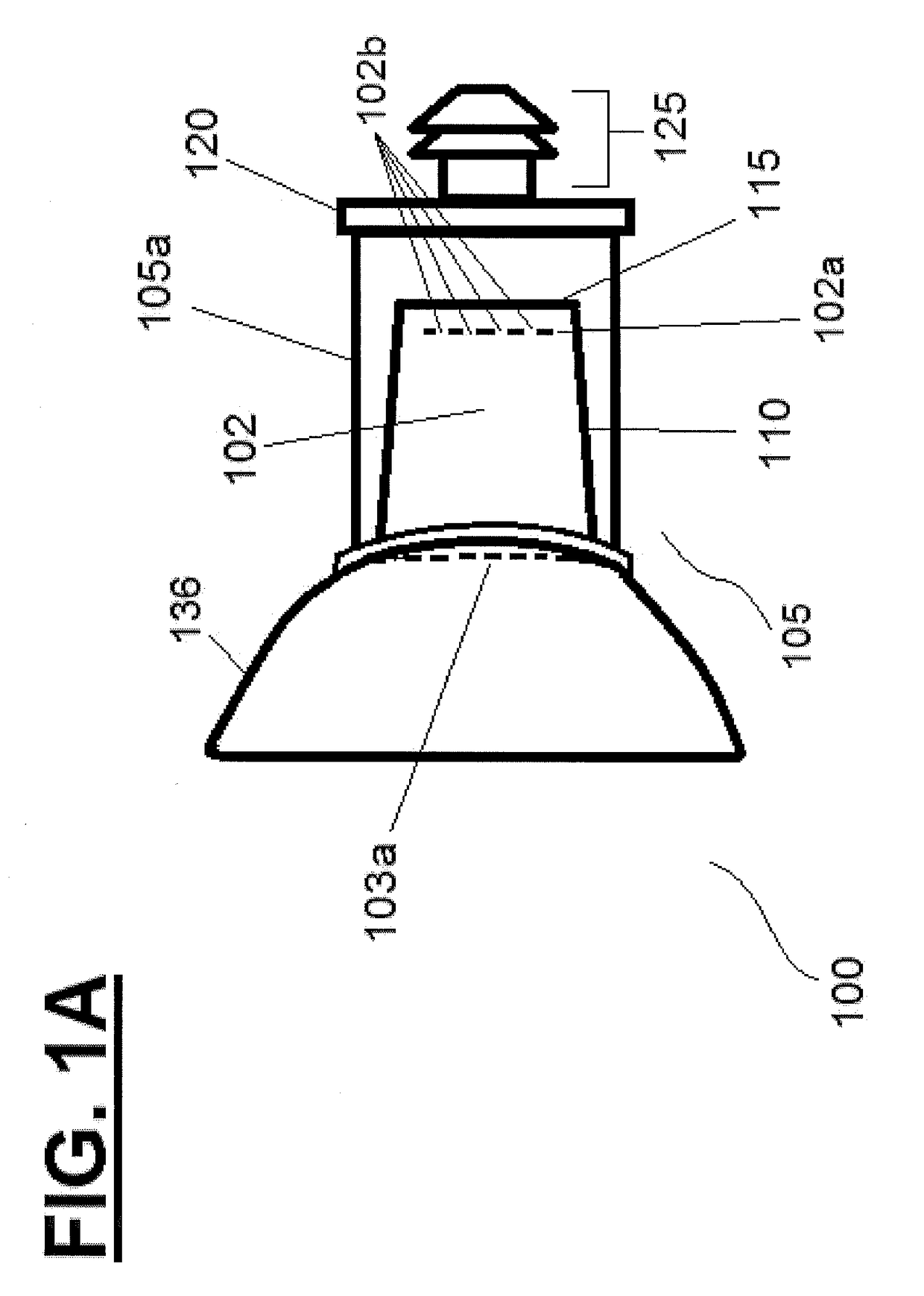
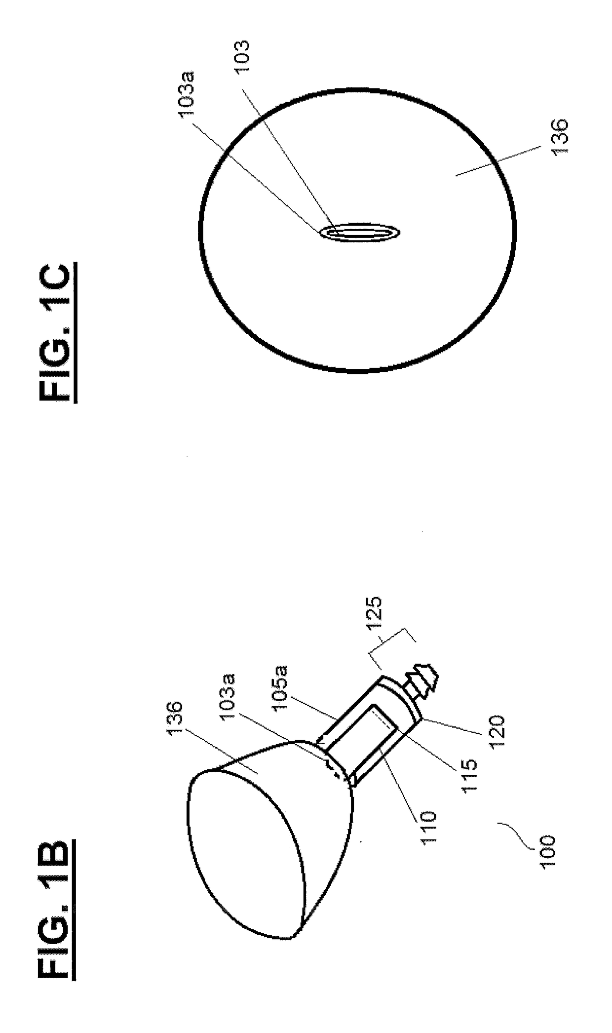
[0055]FIGS. 1A-D collectively show, without limitation, a collection member 100. Referring to FIG. 1A-B, the collection member 100 is made up of a concave receiver 136 (e.g., a cup), a collection valve 105 having a proximal end in fluid connection with concave receiver 136, an...


PUM


Abstract

An external incontinence collection device that includes a novel one-way valve system for preventing backflow from a collection receptacle. The incontinence collection device also includes novel drainage valve structures that improve the drainage functionality.

Description

FIELD OF THE INVENTION[0001]The present invention relates to external incontinence collection devices and methods for using the same. More specifically, the embodiments of the present invention pertain to external incontinence collection devices that may include one-way valve structures for controlling backflow and / or novel drainage valves.DISCUSSION OF THE BACKGROUND[0002]Male urinary incontinence is a common medical problem. Commonly used male urinary incontinence devices include absorbent diapers, invasive urinary catheters and / or external, non-invasive urine collection devices. Each device either subjects the user to adverse health issues. For example, diapers are associated with a high rate of skin breakdown and ulcer formation while indwelling urinary catheters are a cause of urinary tract infections (UTI). Accordingly, there is a great demand for non-invasive external incontinence devices for collecting urine from males without that does not cause skin break down or UTI.[0003...

Claims


Application Information

Patent Timeline
Patent Type & Authority Applications(United States)
IPC IPC(8): A61F5/453A61F5/44A61F5/441
CPCA61F5/453A61F5/441A61F5/4408A61F5/4407A61F5/44A61F5/4404A61F5/4405
Inventor PIERSON, KENNETH
Owner PIERSON KENNETH
Why Eureka
Try Eureka