Cavitated insulating support base for hot water tank

a technology of cavitation and insulating support, which is applied in the direction of fluid heaters, rigid containers, bottle holders, etc., can solve the problems of heat loss in the bottom end of the tank, insulation wool does not extend fully to the bottom of the casing, and energy inefficiency

Inactive Publication Date: 2001-07-31
MICLAU S R I
View PDF5 Cites 42 Cited by
  • Summary
  • Abstract
  • Description
  • Claims
  • Application Information

AI Technical Summary

Benefits of technology

According to the above features, from a broad aspect, the present invention provides a hot water tank is comprised of a cylindrical disc-shaped support base on which is supported a cylindrical inner tank concentrically therewith. A circumferential ridge projects upwardly adjacent an outer peripheral edge of the support base and spaced from a lower edge portion of a circumferential side wall of the inner tank to form a circumferential containment channel between the ridge and the lower edge portion. The channel has a volume sufficient to receive a lower portion of a plastic film pouch wrapper disposed at least about a lower section of the inner casing as well as a predetermined quantity of hot expandable liquid urethane placed therein in sufficient quantity to fill a space between the inner casing and an outer shell secured spaced about the inner casing when the urethane is expanded. The channel prevents the liquid urethane from flowing out of the lower portion of the wrapper located therein due to deterioration of the wrapper when exposed to the hot liquid urethane.

Problems solved by technology

With these methods of insulation, it has been found that, in most cases, the insulating wool does not extend fully to the bottom of the casings and voids are created between the inner casing and outer casing adjacent the support disc spacing peripheral flange and elsewhere.
Tests have shown that these voids in the side wall insulation results in heat loss in the tank bottom end and, therefore, energy inefficiency.
However, this was time consuming because the urethane foam had to be scrapped away from the inside wall of the inner casing.
The wrappers are formed of plastic film material and have one major disadvantage, that being that when the hot urethane is injected therein the wrapper bursts or melts due to the excessive heat of the liquid urethane which exceeds beyond the melting point of the wrapper and some of the urethane flange between the wrapper and the inner tank wall and between the wrapper and the outer casing at the base portion of the wrapper.
This is very time consuming and costly.
It is also well known in the art that bacteria contamination of water in hot water heaters is susceptible in the lower end of the hot water heater where the temperature of the water is at its lowest.
However, this has proven difficult.
It is therefore essential that the lower portion of the tank be properly insulated and this has been heretofore difficult to achieve due to the insulating methods utilized during the fabrication of hot water heaters.

Method used


Image

  • Cavitated insulating support base for hot water tank
  • Cavitated insulating support base for hot water tank
  • Cavitated insulating support base for hot water tank

Examples


Embodiment Construction

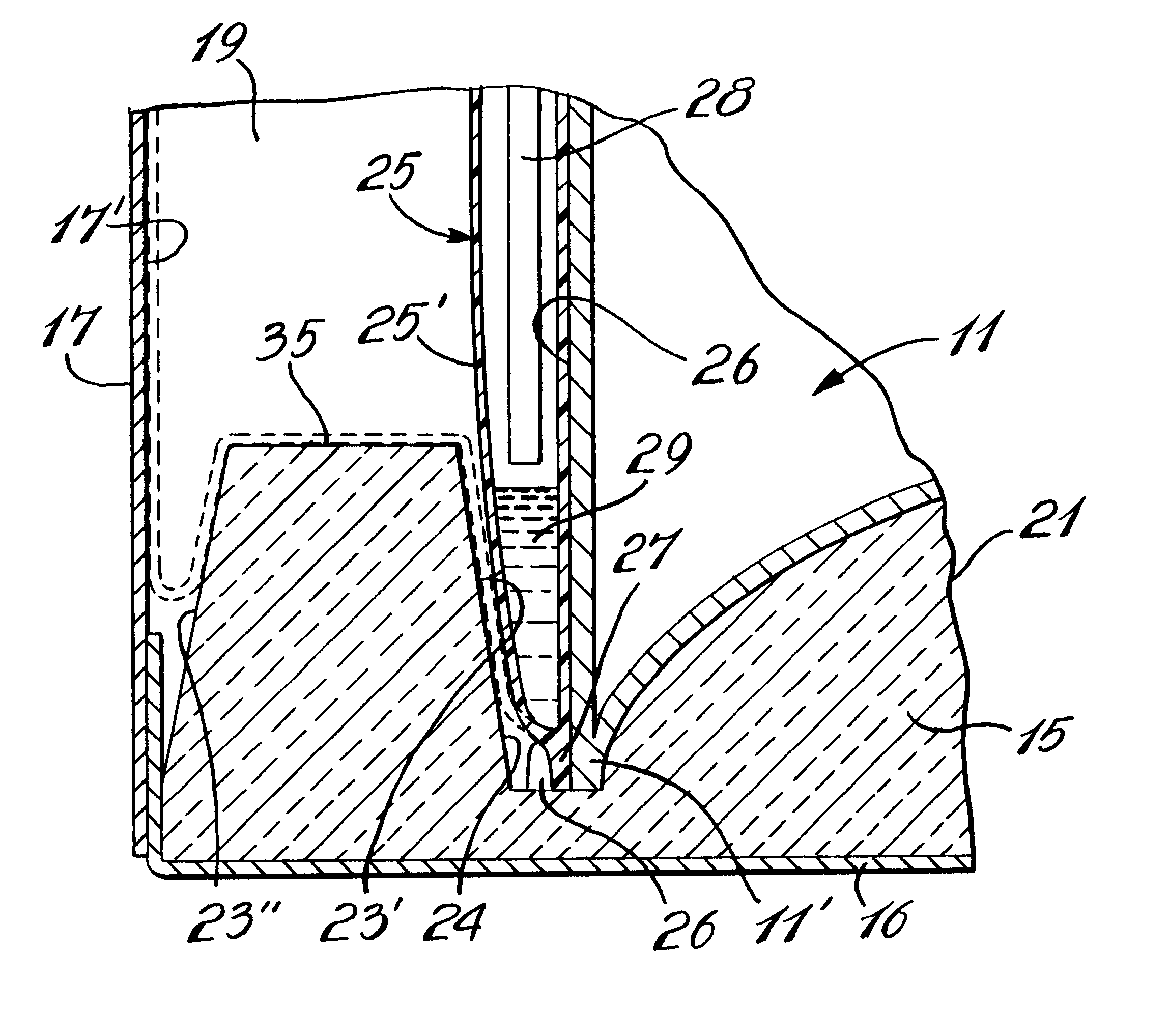
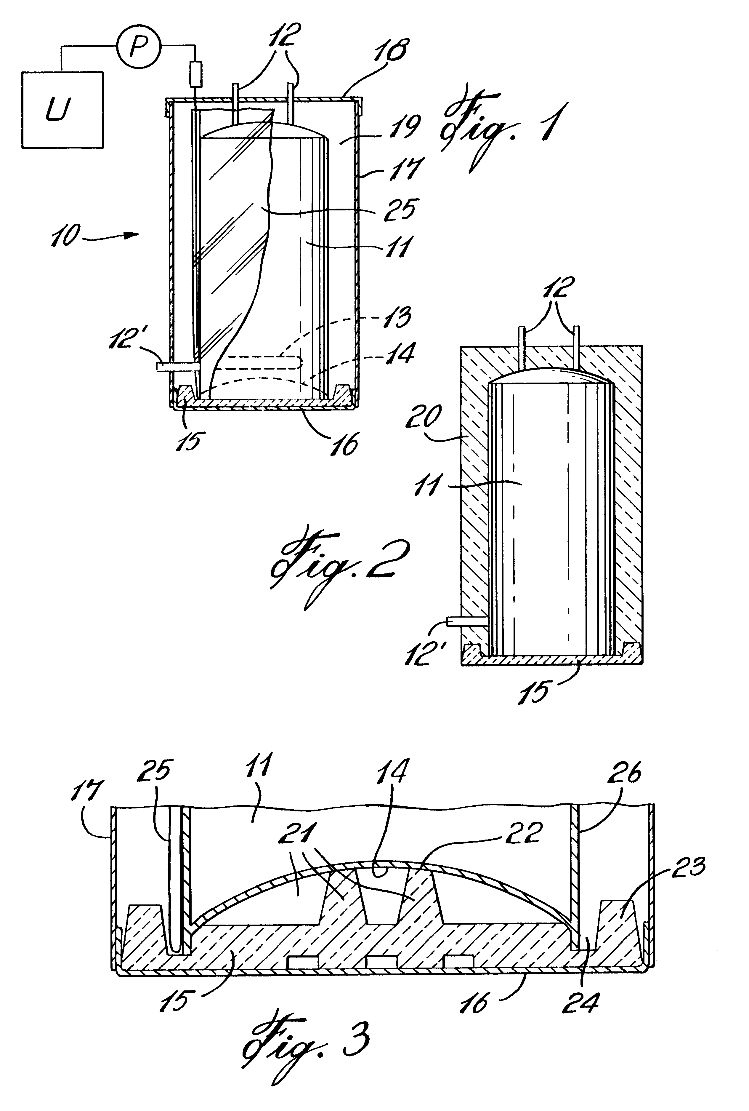
Referring now to the drawings and more particularly to FIG. 1 there is shown generally at 10 the basic construction of a hot water tank. It comprises an inner tank 11 in which water is heated by a heating device not shown, such as electrical resistive elements or a burner mounted in the base of the hot water tank, as is well known in the art. The inner tank 11 is provided with pipe fittings 12 or other fittings such as 12' which lead to the internal resistive elements 13, herein shown in phantom lines located inside the inner tank. The inner tank 11 has a dome shape bottom wall 14 and the inner tank sits on a insulating support base 15, the construction of which will be described later. The insulating support base is positioned for close fit within a pan 16 about which is secured the cylindrical outer casing 17. A top cover 18 is secured over the top end of the outer casing 17. The side wall and cover are spaced from the outer wall of the inner tank 11 to define an insulating space ...


PUM


Abstract

A hot water tank is comprised of a cylindrical disc-shaped support base on which is supported a cylindrical inner tank concentrically therewith. A circumferential ridge projects upwardly adjacent an outer peripheral edge of the support base and spaced from a lower edge portion of a circumferential side wall of the inner tank to form a circumferential containment channel between the ridge and the lower edge portion. The channel has a volume sufficient to receive a lower portion of a plastic film pouch wrapper disposed at least about a lower section of the inner casing as well as a pre-determined quantity of hot expandable liquid urethane placed therein in sufficient quantity to fill a space between the inner casing and an outer shell secured spaced about the inner casing when the urethane is expanded. The channel prevents the liquid urethane from flowing out of the lower portion of the wrapper located therein due to deterioration of the wrapper when exposed to the hot liquid urethane.

Description

The present invention relates to a hot water tank cavitated insulating support base which defines a containment channel to receive a lower edge portion of a plastic film wrapper in which is injected hot liquid urethane whereby to contain the liquid urethane in the lower portion of the bag when injected thereto to prevent the quickly expanding urethane from flowing out of the wrapper and out of the outer casing through crevices provided around pipe fittings or other areas of the outer shell.Description of Prior ArtInsulation support bases for hot water tanks are known. In my U.S. application Ser. No. 826,603 entitled "Insulating Support Base for a Cylindrical Electrical Hot Water Tank", now U.S. Pat. No. 5,178,351 issued Jan. 12, 1993, I disclose the construction of an insulating support base formed of rigid insulating foam material whereby to support the bottom wall of the inner casing of a hot water tank and to facilitate centering of the outer casing thereabout. U.S. Pat. No. 5,18...

Claims


Application Information

Patent Timeline
Patent Type & Authority Patents(United States)
IPC IPC(8): F24H1/18
CPCF24H1/182
Inventor LESAGE, CLAUDE
Owner MICLAU S R I
Why Eureka
Try Eureka