Rapidly convertible hybrid aircraft and manufacturing method

a hybrid aircraft and rapid technology, applied in the field of roadable aircraft, can solve the problems of affecting the operation of the operator's visibility, and affecting the folding and storage of the wings

Inactive Publication Date: 2013-02-12
EASTER WILLIAM CRAIG
View PDF70 Cites 43 Cited by
  • Summary
  • Abstract
  • Description
  • Claims
  • Application Information

AI Technical Summary

Benefits of technology

[0016]The roadable aircraft of the present invention solves the problems of the Prior Art in that it is easy to convert from aircraft to a roadable vehicle, by the push of a button. The single wing is stored longitudinally in the fuselage and is only slightly wider than the cord of the wing. The wings pivot into the fuselage in a novel way using a novel pivoting mechanism, which provides a compact aircraft for storage and roadwork. A single-piece wing is rotatably mounted on the lower portion in the fuselage, which provides a lower center of gravity. The wing is mounted on a pivot may be skewed in any direction to control the final retracted position of the wing. The center of gravity is changed by the pivotal movement of the wing to a preferred location for roadwork and is in the proper location for flight in the extended position.
[0017]As the wing is rotated, a preferred change in CG is also accomplished. Fuel can transfer from the high wing (rear) to a lower wing for the purpose of moving the CG to a preferred location for roadwork. The volume of tail area is sufficient to provide easy flight even from unskilled pilots. The aircraft may have 3 or 4 wheels in connection with the ground for landing or takeoff and operates equally as well for ground or air operation. In a preferred embodiment, three wheels are used, so the vehicle can be registered as a motorcycle, and avoid many safety and emissions requirements for four-wheeled vehicles. The aircraft is highly manufacturerable and is simple in construction. The Pilot and passengers may enter the cockpit with out the aid of steps or ladders. Visibility remains the same during road or flight operations.
[0018]The primary forward propulsion is from the thrust producer, either propeller or turbine. The wing tips or portion of the wing retracts for the purpose of storage or roadwork and reduced drag in flight. The wing is under the propeller in road operation, which prevents stones from entering the propeller during ground operation and keeps pedestrians out of the propeller plane. The booms of the tail are slightly wider than the wing and protect the wing and control structure during ground operation. The aircraft of the present invention may enter the current transportation system of both road and air. The aircraft may be provided with telescopic twin booms supporting the tail, which may be retracted for road use. The aircraft may also be able to vary the wing area by providing retractable wing tips or ends.

Problems solved by technology

Roadable aircraft present many design challenges.
The folding and storing of the wings presents particular difficulty.
If the wings are folded forward to a preferred center of gravity (CG) location, then the wing may block the visibility of the operator.
If the wing is stored on top of the vehicle, gusts from passing trucks may blow the vehicle over on the ground.
However re-attaching the wings in less than perfect weather conditions provides difficulty even for trained personnel.
Some Prior Art Roadable aircraft, such as the Aerocar, towed the wing and tail along in trailer fashion, which created additional problems, such as clearance and susceptibility to cross-winds on the road.
Complex folding mechanisms are prone to failure, require maintenance, and are heavy.
Wings and flying surfaces dangling off the aircraft provide poor aesthetics for the vehicle.
The principle problem is that there is a mix between the roll and yaw axis in the separate vehicles.
Another problem is in the layout of road and flying controls.
Other have the controls located outside or mixed between existing controls, causing possible confusion in emergency situations.
More than 70 auto-planes have been designed and patented over recent decades but all seem to have complex structures which are incapable of quick and convenient conversion from plane to road vehicle and vice versa.
While this allows a pilot to “fly” his auto, it requires complicated folding stock for aircraft controls, fuselage tilting or jacking, airport storage area for the fuselage which must be left behind and return to the point of landing for further flying.
However, the Miller device has complicated fold away wheels and has wings that fold away in a complicated and complex fashion, namely, the front wings must be rotated about a fixed line 90 degrees from horizontal surface to vertical surface, and also be swung into the side of the vehicle 90 degrees, and must be folded in half along their lengths, requiring rotatability, lengthwise foldability and upward swivelability.
This Prior Art auto-plane is very complex and, while it embodies the basics of wing hingeability, locking pins and folding mechanisms, it illustrates vividly what an auto-plane should not be if it is to be convenient, practical, cost effective, and safe.
Unfortunately, the folded wings must overlap one another in their storage slot and so must move up or down as they are swung in so as to render one partially over the other.
Unfortunately, these twice folded stored vertical wing portions render the auto-plane very top heavy.
Further, they create the need for significantly more hardware, hinges, locking mechanisms, and create a four-wing thick top clearance problem.
Not only are complex wing movements required, but also the wing support struts are cut and hinged so as to break and swing inwardly in an awkward and broken path.
Zuck requires substantial, complex fold up hardware typical of the prior art.
Unfortunately, storage of the wings for road use requires a complex. series of three different motions and the necessary hardware, hinges and latches to achieve these.
This method leaves the delicate control surfaces in a position which is likely to be damaged.
Einstein, U.S. Pat. No. 4,627,585, incorporated herein by reference, discloses a Telescopic tail section but fails to teach a method of deployment and method to synchronize its movements in order to prevent binding.
In the absence of a synchronizing method one side even slightly out of alignment due to wear or manufacturing tolerances will bind and not function properly.
Further the stator and rotor are not optimized for maximum torque.

Method used


Image

  • Rapidly convertible hybrid aircraft and manufacturing method
  • Rapidly convertible hybrid aircraft and manufacturing method
  • Rapidly convertible hybrid aircraft and manufacturing method

Examples


Embodiment Construction

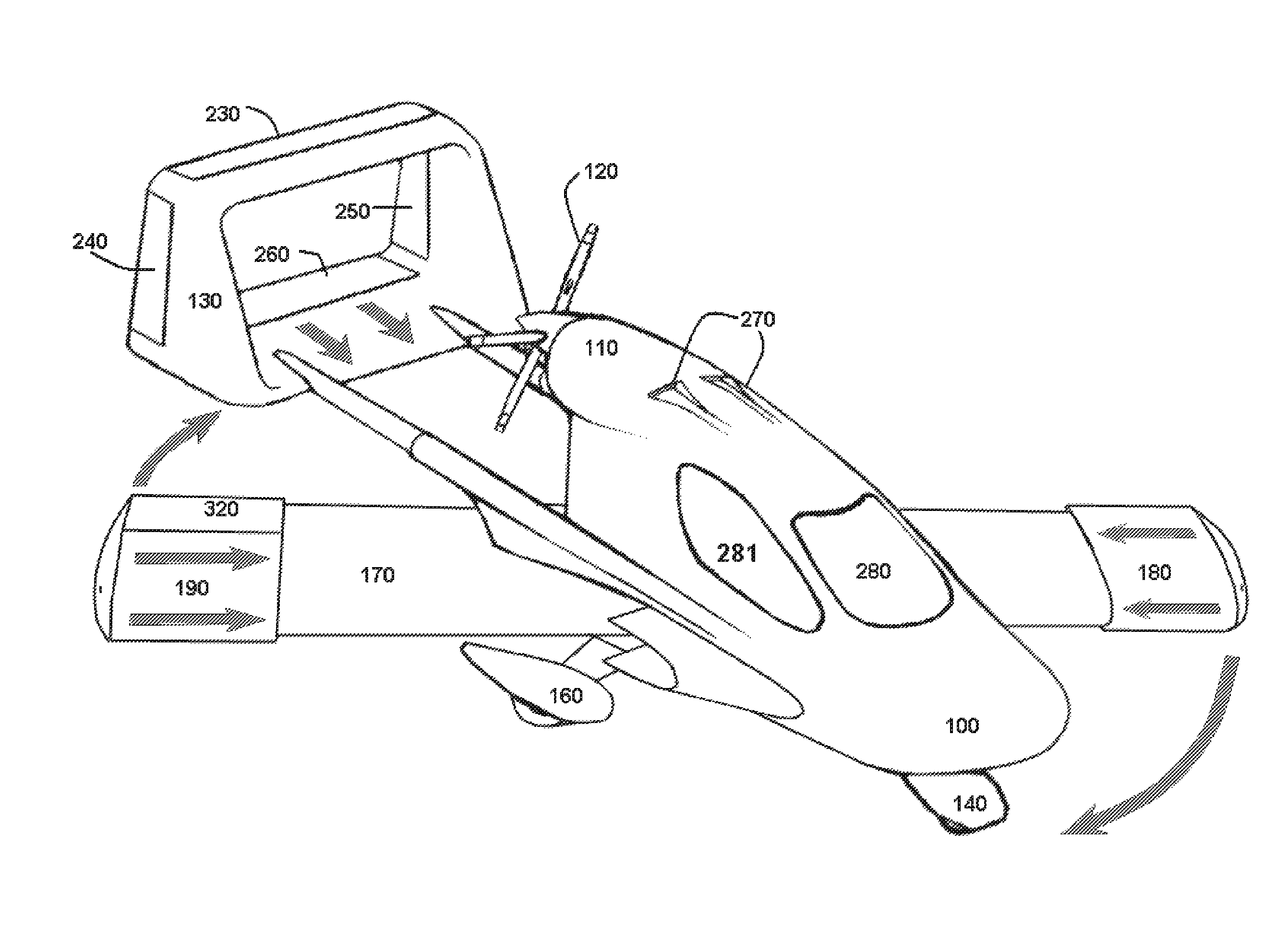
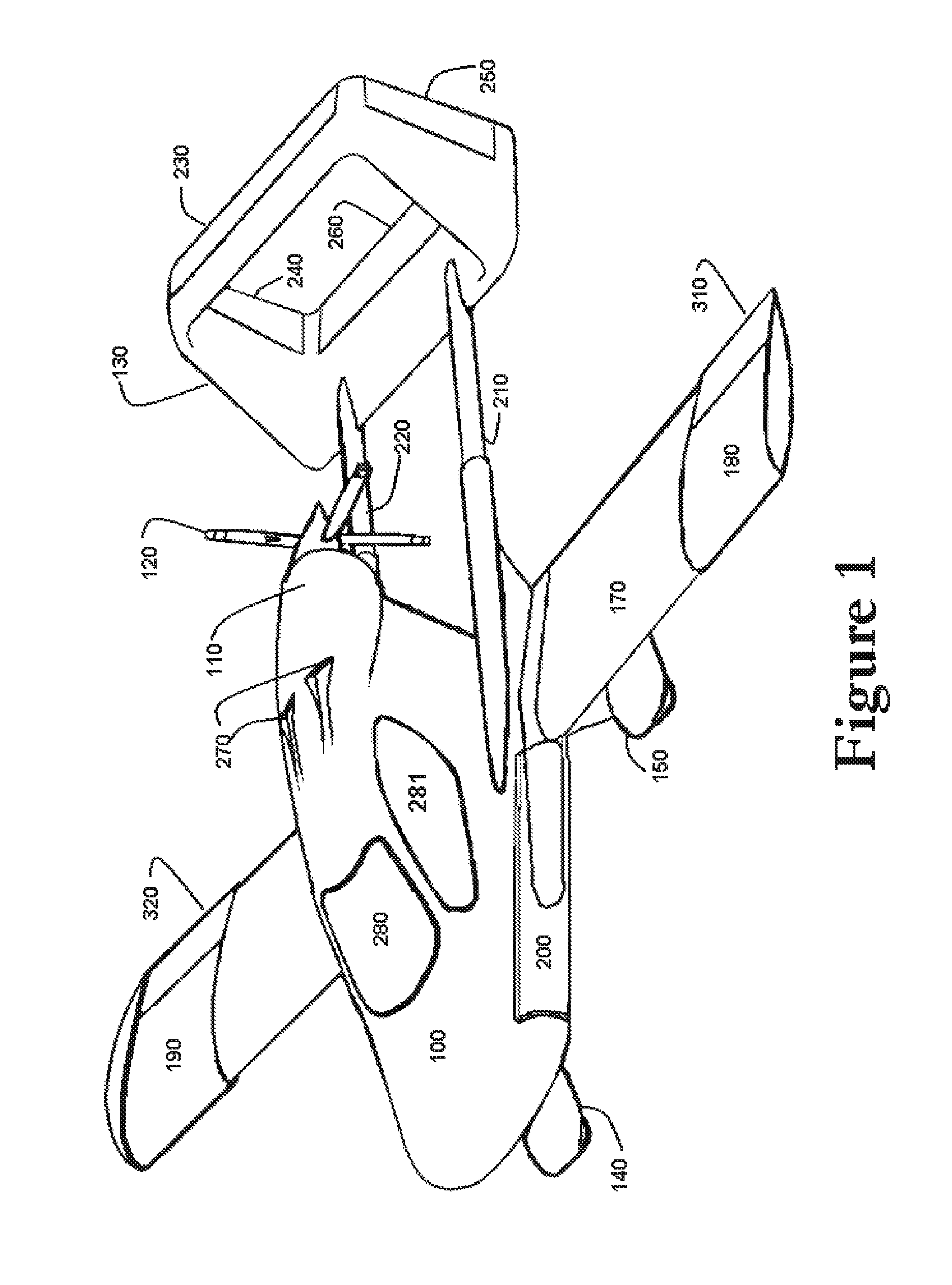
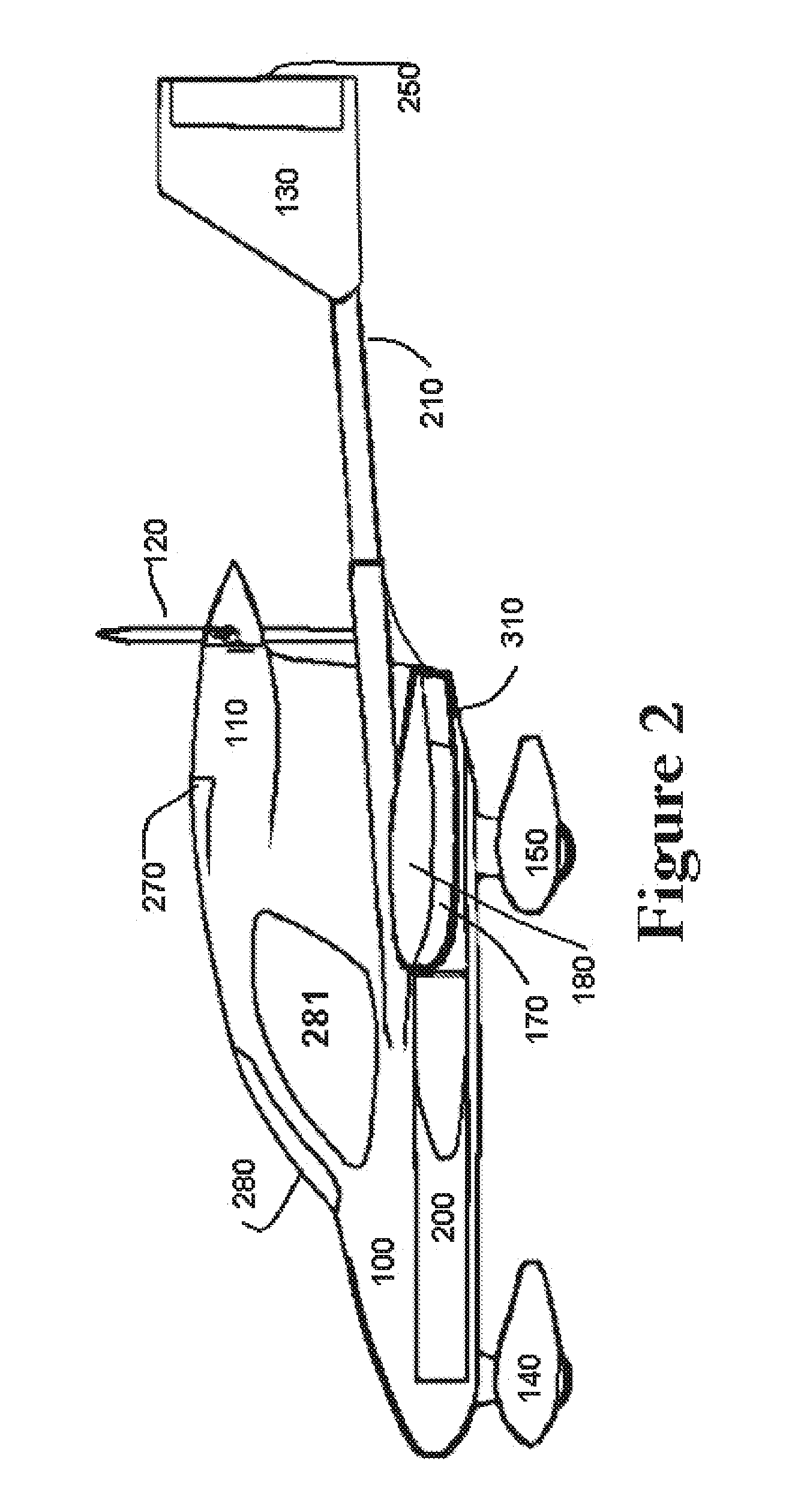
[0047]Referring to FIGS. 1-9, the preferred configuration for roadable aircraft of the present invention is a two-seat aircraft 100 with a pusher propeller 120, twin booms 210 and 220, a box tail 130 and a low wing 170. A preferred configuration is such that the Empty weight is below 1500 pounds so that the vehicle may be licensed in all States as a 3-wheel motorcycle and also possibly as a light sport aircraft if below 1320 pounds. The twin boom configuration 210, 220 keeps the propeller 120 within a well-protected area such that pedestrians cannot easily enter the plane of rotation. The wing 170 in the retract position is located under the propeller 120 to prevents stones and debris from entering the propeller 120 and in combination with the twin booms 210, 220 help to prevent pedestrians from entering the plane of rotation, providing a ground-safe vehicle. The box tail 130 further helps in this area. It is important for the vehicle to have a low wing 170 in order have a low CG. T...


PUM


Abstract

A hybrid fixed wing aircraft converts into a roadworthy vehicle in a matter of seconds therefore operating efficiently in both air and ground transportation systems. The single piece wing is mounted on a skewed pivot that is on the lower portion of the fuselage and is operated by a pushbutton operating system. The aircraft includes telescopic twin boom tail design that when extended allows good pitch stability and damping. The aircraft's wing area may be increased with additional telescopic wing tip segments. This allows an increase in aspect ratio, hence improving efficiency at high loads. This feature also creates a reduction in induced drag at cruise speed by simply retracting the tips in flight. The vehicle has a unique synchronized control system that switches from flight to ground mode without input from the operator, thereby providing a natural interface for the operator.

Description

CROSS-REFERENCE TO RELATED APPLICATIONS[0001]The present application claims priority from Provisional U.S. Patent Application Ser. No. 61 / 230,307 filed on Jul. 31, 2009 and incorporated herein by reference.FIELD OF THE INVENTION[0002]The present invention relates to a roadable aircraft, or aircraft that can change shape on the ground or in the air. In particular, the present invention is directed toward an aircraft that can quickly convert to an automobile or motorcycle.BACKGROUND OF THE INVENTION[0003]Roadable aircraft present many design challenges. For example, the craft must be small enough in its retracted or folded position to fit within (standard) garages, drive-up facilities and parking facilities, which limits the principle dimensions to a volume of 20 feet by 7 feet by 7 feet. In order to fit within the current transportation system to avoid heavy glass and all wheel braking, the craft should be below 1500-pound empty weight (curb weight) and licensed as a 3-wheeled motorc...

Claims


Application Information

Patent Timeline
Patent Type & Authority Patents(United States)
IPC IPC(8): B64C37/00B64C27/24B64C3/56B64C9/34
CPCB60F5/02B64C3/56B64C5/02B64C13/30B64C25/405B64C37/02B64C39/04Y02T50/145Y02T50/44Y02T50/823Y02T50/10Y02T50/80Y02T50/40B64C37/00
Inventor EASTER, WILLIAM CRAIG
Owner EASTER WILLIAM CRAIG
Why Eureka
Try Eureka