Dispenser having non-frustro-conical funnel wall

a funnel wall and funnel wall technology, applied in the field of atomizers, can solve the problems of increasing or decreasing the cone angle, affecting the flow rate of current atomizers, and not always providing a sufficiently small particle size distribution

Active Publication Date: 2015-11-03
PROCTER & GAMBLE CO
View PDF34 Cites 63 Cited by
  • Summary
  • Abstract
  • Description
  • Claims
  • Application Information

AI Technical Summary

Problems solved by technology

However, current atomizers do not always provide a sufficiently small particle size distribution, particularly at relatively low propellant pressures.
Lefebvre further acknowledges that a major drawback of the simplex atomizer is that flow rate varies with only the square root of pressure differential.
Another problem with atomizers found in the prior art is that to increase or decrease the cone angle of the spray pattern using an atomizer having the straight sidewalls of the prior art requires rebalancing various flow areas, (e.g. swirl chamber diameter, tangential flow area, exit orifice diameter or length / diameter ratio).

Method used


Image

  • Dispenser having non-frustro-conical funnel wall
  • Dispenser having non-frustro-conical funnel wall
  • Dispenser having non-frustro-conical funnel wall

Examples


examples

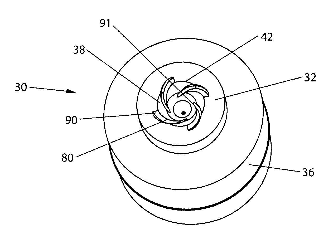
[0073]Three different spray systems were tested. The first sample 100 utilized the helix cup 30 of FIGS. 3-3B and 5-8. This helix cup 30 had four grooves 80, an approximately 64 degree included angle, and an outlet 40 having a diameter of 0.18 mm. The ratio of the flow area of the grooves 80 to the flow area of the nozzle 32 is approximately 7.5:1.

[0074]The second sample 200 is a commercially available Kosmos spray actuator sold by Precision Valve Co. having an orifice diameter of 0.18 mm.

[0075]The third sample 300 is a helix cup 30 having the same groove 80 geometry, outlet 40 diameter of 0.18 mm, same flow area ratio of approximately 7.5:1, and the same included angle of approximately 64 degrees. But the third sample had the frustro-conical funnel wall 38, discussed by Lefebvre. The funnel wall 38 of sample 300 was approximately 20 percent greater than the corresponding area of the funnel wall 38 of sample 100.

[0076]Each sample 100, 200, 300 was loaded with 50 ml of deodorant spra...


PUM


Abstract

A helix cup for use in a pressurized dispenser. The helix cup has a convergent funnel wall. The funnel wall is not straight and does not satisfy the mathematical equations for surface area or for subtended volume of the frustrum of a cone. Instead, the funnel wall provides a longer flow path than is achieved with straight sidewalls. The longer flow path provides for a tighter particle size distribution at lower pressures than occurs in the prior art.

Description

FIELD OF THE INVENTION[0001]The present invention relates to atomizers for use with fluid spray devices and more particularly to atomizers suitable for producing relatively small particle size distributions.BACKGROUND OF THE INVENTION[0002]Fluid atomizers are well known in the art. Fluid atomizers are used in sprayers to atomize a discrete quantity of liquid being dispensed. The liquid may be stored in bulk form in a reservoir 22. A manual pump or propellant charge may be used to provide motive force for drawing the liquid from the reservoir 22, to the atomizer and spraying through a nozzle. Once the liquid is sprayed through a nozzle is may be dispersed to the atmosphere, directed towards a target surface, etc. Common target surfaces include countertops, fabric, human skin, etc.[0003]However, current atomizers do not always provide a sufficiently small particle size distribution, particularly at relatively low propellant pressures. Relatively low propellant pressures are desirable ...

Claims


Application Information

Patent Timeline
Patent Type & Authority Patents(United States)
IPC IPC(8): B05B1/34
CPCB05B1/3442B05B9/007
Inventor SMITH, SCOTT EDWARD
Owner PROCTER & GAMBLE CO
Why Eureka
Try Eureka