Remote terminal thermostat

a remote terminal and thermostat technology, applied in the field of remote terminal thermostats, can solve the problems of preventing some employees from initiating local overrides, difficulty in finding a single location, electromechanical solutions lack the flexibility of a full digital solution, etc., and achieves convenient local overrides, simple centralized building controllers, and convenient local overrides.

Active Publication Date: 2015-11-03
GRIDPOINT
View PDF6 Cites 7 Cited by
  • Summary
  • Abstract
  • Description
  • Claims
  • Application Information

AI Technical Summary

Benefits of technology

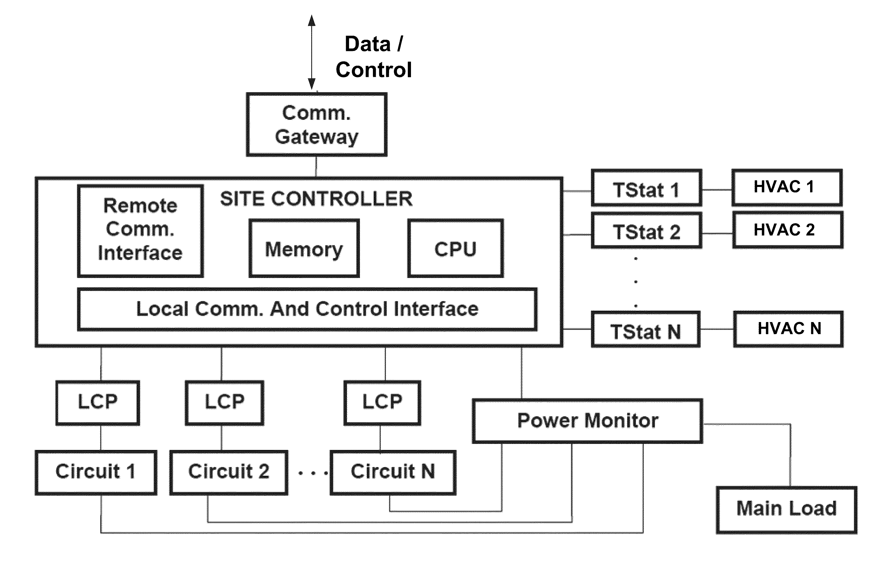
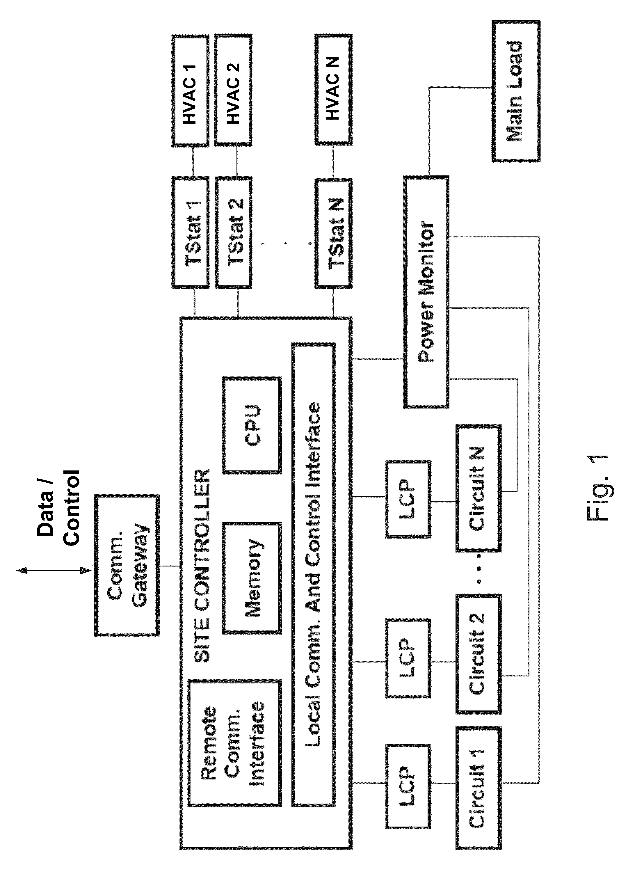
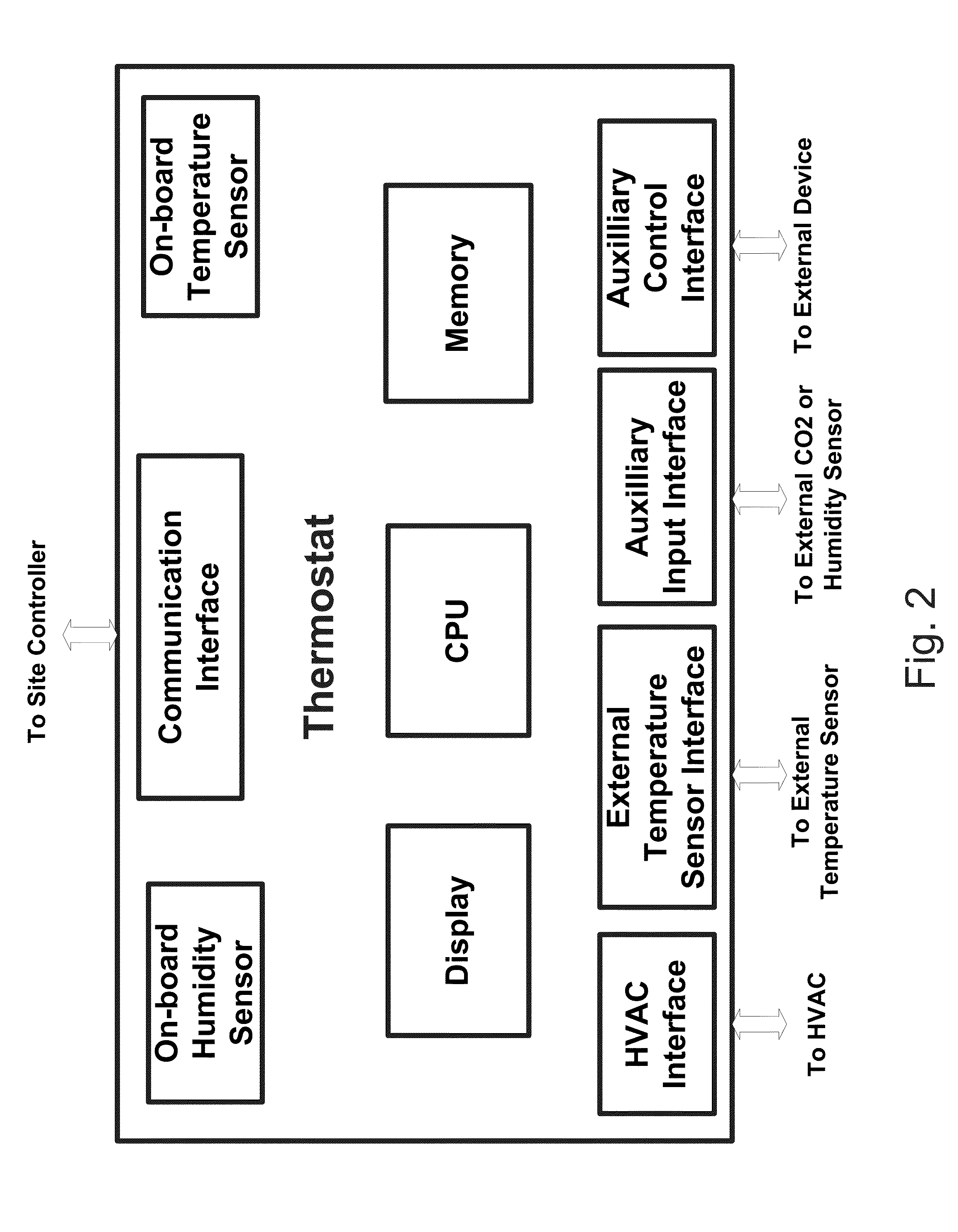
[0006]What is needed is an onsite energy management system that offers a convenient, flexible, and inexpensive means of reviewing operational data and making override changes to any of the HVAC or lighting control devices from any zone. To that end, one or more thermostats are provided with terminal mode operation that gives users a means to control any HVAC unit and lighting controllers from any thermostat display. The thermostat includes a touch screen that provides an interface for requesting temporary override control of building lighting and HVAC set points, as well as reporting the state of the system. Change requests transmitted by the thermostats are merged with the system state at the central site controller, which determines whether to allow the override and to when to restore the HVAC or lighting controls to the normal set point schedule. This arrangement allows for a simple centralized building controller without the requirement of it having its own display, and further provides inexpensive, flexible, and convenient local override control.

Problems solved by technology

However, it is often difficult to find a single location for the controller / display that allows convenient access by personnel from each zone.
Electromechanical solutions, however, lack the flexibility of a full digital solution.
However, many businesses do not allow all employees to use the computers, thus preventing some employees from initiating local overrides when necessary.

Method used


Image

  • Remote terminal thermostat
  • Remote terminal thermostat
  • Remote terminal thermostat

Examples


Embodiment Construction

[0019]The present invention may be understood more readily by reference to the following detailed description of preferred embodiments of the invention as well as to the examples included therein. Embodiments of the invention provide systems and methods for providing local override control of an EMS. The following description and drawings are illustrative and are not to be construed as limiting. Numerous specific details are described to provide a thorough understanding. However, in certain instances, well-known or conventional details are not described in order to avoid obscuring the description. Reference in this specification to “an embodiment” or “the embodiment” means that a particular feature, structure, or characteristic described in connection with the embodiment is included in at least an embodiment of the disclosure. The appearances of the phrase “in an embodiment” in various places in the specification are not necessarily all referring to the same embodiment, nor are sepa...


PUM


Abstract

An energy management system having a centralized site controller is provided with thermostats in multiple zones, each thermostat having the capability of acting as a remote terminal to the controller. Each thermostat provides an interface to the site controller while simultaneously acting as the thermostat for each zone. The thermostat can display information concerning the state of the building's lighting and HVAC systems for any zone and allow the local user to initiate local overrides of set points. In an embodiment, override requests are received by the central controller and merged with the settings for the current control algorithms.

Description

BACKGROUND OF THE INVENTION[0001]1. Field of the Invention[0002]The invention relates generally to systems and methods of monitoring, controlling, and managing energy usage. More specifically, the invention relates to systems and methods for reviewing and overriding energy management system parameters using a remote terminal unit such as a thermostat.[0003]2. Description of the Related Art[0004]Energy management systems (EMS's) typically control and monitor multiple endpoints such as HVAC units, lighting panels, and / or other power consuming devices, typically located in different areas (zones) of a building. If endpoints are monitored and controlled by a centralized EMS, some local control is also desirable in order to provide local users a system status review and the ability to initiate temporary control overrides in a particular zone.[0005]Local monitoring and control can be performed in several ways. In some systems, the site controller has a display that shows the status and ot...

Claims


Application Information

Patent Timeline
Patent Type & Authority Patents(United States)
IPC IPC(8): G01M1/38G05B13/00G05D11/02G05D11/16G05D3/12G05D5/00G05B15/02G05D11/00G05D7/00G05D9/00G05B15/00G05D23/00F24F11/00
CPCG05B15/02F24F2011/0091G05B2219/2614G05D23/1902F24F11/52F24F11/30F24F11/46F24F11/56
Inventor DYESS, DANIEL K.
Owner GRIDPOINT
Why Eureka
Try Eureka